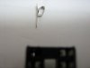
I wouldn't try to change the Socket (all of it or some pins ) yet,
just clean it the best you can.
The main issue is deciding if the IC is Bad or good.
I do think it is Bad, but not yet 100% sure.
You say it is partly working - display is changing when you press something,was this this correct?
If it is Bad ,getting another IC and replacing it isn't very simple (probably not cheap either).
Contact the manufacture and enquire about the IC availability and price,that is of a "burned"/programmed IC (there may be a possibility to get the file to be burned in an "empty" IC).
For that they should be able to identify the model and board exactly...
For now I would do the following:
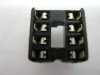
1. Clean the IC and socket the best you can.
2. Carefully insert the IC back into the socket, and watch out for the correct
pin #1 marking!
3. Connect the boards together and power-up.
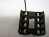
4. On the IC Check DCV between pins 11 and 12 ,and between 32 and 31
(do that directly on the IC pins,not at the board)
5. Watch to see if you can change the display
-that is an indication that the IC is working ,at least partially.
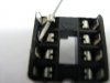
6. Measure the voltages directly on the IC pins (again not at the board)
relative to GND.
Pins 5 to 10( a total of 6 pins) while trying "to make the relays click" using
the remote or what ever button there is on the chair for that thing
(i.e. Back and Leg).
note

ins 5 and 6 are also part of Back/Leg activation .
Let us know what are the results you find.