Maker Pro
Maker Pro

Help! Repairing water damaged PCB from Massage chair.

Let's do an omh continuity test.
0 ohms, if there is continuity .
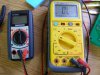
Do the test in DMM ohm range(buzzer if there is one ).

Between same color points (one on IC controller,
Green is a "good realy channel" ,pin #9
REd is the "Bad relay channel", pin #10
Do it like the pic shows(on the componnents legs).
cable connected between the 2 boards.
No power!
what do you get?

View attachment 24063 the athor on resistor):


Nothing. No beep. No continuity. Hope that's good news. I need to hear some already.
Jonathan

Edit: I misread. and did that wrong in the first try. Green Green is probe black and white then Red red is probe red and white too. That's what you meant. Yes there is continuity between those two points.
 
Your post is not clear.
Are you getting 0v only at the bad un-clicking realy?
If so,what do you get at the good one?(2 readings).

Looks like I have not been clear on this. There is no relay I can click with the remote. None. The only way I can make them click is when I put resistor in and connect as shown in post 86. None of those lines had any power when I pushed back up or down on the remote.
 
Looks like I have not been clear on this. There is no relay I can click with the remote. None. The only way I can make them click is when I put resistor in and connect as shown in post 86. None of those lines had any power when I pushed back up or down on the remote.

Please show what do you mean ,I can't understand
Where do you put the "resistor in" ,what value is the resistor you put?
Here is the pic from #86.

PC260037.JPG
 
Ok, I am not sure what value a resistor I used because I use the internal resistance of my ohm meter. I set my multimeter to ohms touched the black probe where the black arrow is and the red I moved around as shown with the red arrows. This turns on the transistors by giving them some small signal.

At least that's how it worked all the other times I tried it. Now I cannot repeat the experiment and make them go on. It worked perfectly till now. I have done it lots of times to see if the relays click after I make changes to stuff. Not sure what's going on now, but will find out.

Jonatan ,
I'm speechless ...o_O
Why would you use an ohmmeter to make the relays click?
What kind of ohmmeter is it ,your DMM?an analog one?

Please don't use the ohmmeter again in future measurements!
It is diverting the understanding of what you do and what is going on.
I was under the impression that you have 3 perfectly working relays circuits and one non-functioning one.
But now you say all 4 are faulty/

Did the remote ever operated any relay(s)?

In the last pic (with both boards connected and powered ) ,
please check the DCV with the DMM related to GND at:
1.The +12V pin on the connector.
2.All the "red points" in "click-state" and "non click-state".


Sorry for that. I thought I was always clear and going back to re-read I still think I said it right. After I shorted the shirt out of relay 1 with my soldering Iron. No relays worked with the remote anymore. Before that event, for sure two of the relays worked. I had the chair's back support operating. I could never get the leg supports to move with the remote.

I learned to switch TRANSISTORS with an Ohm meter through a tube tutorial on how to get transistors working. I was using the ohm meter to switch the transistors which switched the relays. If that is still a bad idea. I was mislead. Sorry.
 
Jonatan ,

please check the DCV with the DMM related to GND at:
1.The +12V pin on the connector.
2.All the "red points" in "click-state" and "non click-state".

The answer is still the same. 0 V when I hold recline button 0V when no button is pushed. I tested all four relays. There is no signal coming from the IC to switch the transistors.
 
"If that is still a bad idea. I was mislead."
Yes it is a bad idea,especially so when the board is powered.
You see, an ohmmeter created voltage will conflict with the board voltage.
Ohmmeter test should always be done with no power!

What about the 12V?is there any voltage there?

Is there any indication that the micro-controller IC is working (partly)?

Please do an ohm test between the "red-points" and GND(no power to the board!),what do you get?

After the shorting incident,did you replace any of the relay driving S8050 Trs?
Was any of them shorted?Do you still have them?
 
16V between GND and +12V

The only indication I have of the IC still working is the fact that air bag massage works. Also the display and icons on the controller if that is any indication. From what I can tell though, the air bag massage is only connected to the IC by one pin. There is a smaller IC that all air bag transistors are connected to.

An OHM test between the res points and ground shows 0 ohms. No connection between them.

I have only replaced one of those transistors. It was for relay 1. I probably still have it on my desk somewhere, but I would have a hard time telling which on it is. The rest are still on the board.
 
"An OHM test between the res points and ground shows 0 ohms. No connection between them."

O.K that means the red points are shorted to GND !
Now remove the cable between the boards ,
and repeat the test on each board separately (in ohm test,not diode).
What do you get?
 
Maybe this will be of some use to somebody. I will try to get the other one done today too. The second will not take as long. Now I know how to do it.
Mains overlay.jpg
 
"An OHM test between the res points and ground shows 0 ohms. No connection between them."

O.K that means the red points are shorted to GND !
Now remove the cable between the boards ,
and repeat the test on each board separately (in ohm test,not diode).
What do you get?


Same result. The measurement stayed at 0.L nothing showed up.
 
Can you show a poho of the DMM you use for ohm test?

Are you saying that on both boards when they are disconnected from each other you are getting 0 OHM red-points to GND?
 
after a slight delay to look for new batteries for my Olympus. No I ran both checks on the same board. One connected the other test not connected. I will recheck right now. Here are my DMMs I have been using the yellow one for everything so far, but I do have the other one available too.

Jonathan
 

Attachments

  • PC290052.JPG
    PC290052.JPG
    289.4 KB · Views: 115
Ok I did that wrong. I was measuring between 12V and the points. Am doing it again. from control board between GND and relay 1, 31.54kΩ, Relay 2. 92.4kΩ Relay 3 3.3mΩ Relay 4 0MΩ. That is with board disconnected. I will do the same test to other board then connect them and do it again.
 
Relay 1. 7.5KΩ Relay 2. 3.8KΩ, Relay 3. 3.99KΩ Relay 4. 3.99KΩ

I went back and re-checked relay four numbering from closest to board as 1 with board disconnected and still got 0
 
Top