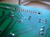
Maker Pro
Maker Pro

Help! Repairing water damaged PCB from Massage chair.

Good Pictures.
We need to find out exactly how those chair elements are connected to the PCBs.
Can you please try to put it all in a "diagram" .

By CS in the previous post I meant the component side of the PCB you soldered and caused the problem you have now (post #41).
Knowing them may help us find out what can be the cause of the fault.
 
OH, Shucks. I didn't realize I hadn't posted pictures of the other side of that Mains board. I will get them up right away. All the components on the chair are marked in red on the boards linked in this post.
102_0542.JPG 102_0543.JPG
 
The big caps on the mains board are very slightly domed. As shown in this picture. I have a capacitor test feature on my Muli-meter. Is this reliably enough? Should I pull those caps and test them?PC260017.JPG
 
The big caps on the mains board are very slightly domed. As shown in this picture. I have a capacitor test feature on my Muli-meter. Is this reliably enough? Should I pull those caps and test them?View attachment 24009

What is the value and voltage of the cap?
In general ,you can test caps in circuit .
It is very important to discharge them properly. please,don't try that yet !
 
OH, Shucks. I didn't realize I hadn't posted pictures of the other side of that Mains board. I will get them up right away. All the components on the chair are marked in red on the boards linked in this post.
View attachment 24007 View attachment 24008

Did you change that relay?
It looks like a 24V relay,and I think the "original" blue ones are probably 12V.
Is this so? can you check the voltage on the relay coil to gnd?

The S8050 NPN transistor near it(marked blue in the pic) needs testing,
you can test it in-circuit and compare with the 3 similar ones below it.
without power, in diode ohm mode(a possible C-E short,but do a full test)

102_0542.JPG
 
Jona,
Can you please repeat what is the current time fault(I can't find it above...).
Actually all the S8050 needs checking.
I think the upper (2 tr +2 relays) are for Leg
and the bottom ones are for back.
 
Jona,
Can you please repeat what is the current time fault(I can't find it above...).
Actually all the S8050 needs checking.
I think the upper (2 tr +2 relays) are for Leg
and the bottom ones are for back.


You are correct. If you look at the CN31 with the lower set of relays it is fir Back up?DW CN14 with the upper set of relays is for Leg up/Down. I did change out that Black relay and you are right it is a 24V relay. I put it in temporarily before somebody shut down my soldering on this board. I wanted to see if this one would click on because the original blue did not after the accident with my soldering Iron. I think the original 12V may still be OK.

The fault right now is that I cannot get any of the relays to click on with the remote anymore. The remote does the chirping it did before when I activate Back or leg up/down but the relays don't click.

A note not the S8050 transistors. As I said in a previous post, the S8050 are NPN transistors. I think only one or two of those transistors are actual S8050. I had a pile of transistors here that I ran through my transistor tester. Those that came up as NPN and the same as the original S8050 I put on a pile and used as replacement for the originals which had rusted off leads. They all worked before I shorted things to heck with my soldering Iron. You say I can test them in circuit. I will try to do that, but I will need a better explanation as to how to do that. While I wait for you to get back to me on this I will try to look it up somehow.

Jonathan
 
Ok I re-read your note to test the NPN transistors in diode ohm mode. I take it that's the diode symbol on my DM384 Digital Multimeter. When I test them I was surprised at the range of V I found in all those transistors. From 1.4 V. to .6 V.

Also Interestingly, the transistor that goes to the heat unit read 0. V.

I guess the next thing you will say is that I need to get a pile of transistors? I'm beginning to think I should prepare an order from Digikey if there are enough components that I need to get replaced here, it would make more sense to do it that way. It's a lot cheaper once you get more components that need to be replaced. I will post some more pictures in a minute here.
 
I took some pictures of the leads to some of the transistors I haven't replaced. Keep in mid that these are transistors that have been shown to work when I power up the board and try it. The 6 TP122 transistors for the solenoids all work perfectly. I am unsure of the status of the two Larger K1358 components. (the markings on the board below them say K1120). Would it be OK to re-tin the leads of these transistors if they are still working to protect them for further corrosion or should they be replaced outright?


PC260020.JPG PC260021.JPG PC260022.JPG
 
In the mean time. I have been keeping busy practicing my soldering. Here are some examples. The poor relay in the centre of picture 1 has been out and in three times. The row of solder is a bank of plugs that has been out and in a few times also.

The solder wick works fine with a little bit of Soldering Paste on it. I have been cleaning off my solder with a drop or two of Solvent and a toothbrush. looks good now.

The soldering past I discovered in a drawer is pictured here. From what I gather from the soldering video this is not exactly the stuff I should be using for this job but for now it's all I have and it does the trick. Any good reason not to use it till I get proper flux from the store?

Jonathan
 

Attachments

  • PC260032.JPG
    PC260032.JPG
    195.4 KB · Views: 93
  • PC260034.JPG
    PC260034.JPG
    242.8 KB · Views: 79
  • PC260033.JPG
    PC260033.JPG
    204 KB · Views: 95
In the mean time. I have been keeping busy practicing my soldering. Here are some examples. The poor relay in the centre of picture 1 has been out and in three times. The row of solder is a bank of plugs that has been out and in a few times also.

The solder wick works fine with a little bit of Soldering Paste on it. I have been cleaning off my solder with a drop or two of Solvent and a toothbrush. looks good now.

The soldering past I discovered in a drawer is pictured here. From what I gather from the soldering video this is not exactly the stuff I should be using for this job but for now it's all I have and it does the trick. Any good reason not to use it till I get proper flux from the store?

Jonathan

Your soldering is much better,are you still using the 1mm solder?
It will be much better with a 0.6mm one.
I did notice a slightly lifted pad on the connector.

The Solder paste looks from another era.
It could be very acidic,use it for now and clean the residues very well after.

As for the board
Leave the CAP alone for now.
Lets concentrate on the 4 relays'please look at the pic

I finally found some time to dig into the problematic area.
There is probably a diode close to each of the relay coils,can you confirm that.

RED is functional devices.
Blue is what caught my eye for soldering inspection/shorts.

The violet color is for you to test: DCV with the DMM
Be very careful not to short while probing and do not tuch the higher voltage areas.

It is a very basic 4 relay drive from the Controller.
The voltage is +12V created on the controller board by a voltage regulator IC.

1.Look for 12VDC on the connector from the controller board.
2.With all "commands off" there should be 12VDC between all tr. C-E and 0VDC between B-E
3.With command "on" there should be 0.3VDC Tr. C-E and about 0.7VDC between B-E and about 5V on the matching control pin on the connector
(I think #3 will fail).

102_0533.JPG
TR -relay.JPG
 
Ok. good to see life again here. I, in the mean time have been busy looking at my old solder on the board. I used wick to take off solder along the transistor line and the optocouplers. I found a lot of pads that were not there under my solder. I am slowly building them up again and doing surgery where needed. I found thinner solder too BTW. I will begin looking at the areas you highlighted.
 
Have you got deoxit?
It can help with connectors cleaning etc.

Bed time for me,talk to you tomorrow.
Take care
 
Your soldering is much better,are you still using the 1mm solder?
It will be much better with a 0.6mm one.
I did notice a slightly lifted pad on the connector.

The Solder paste looks from another era.
It could be very acidic,use it for now and clean the residues very well after.

As for the board
Leave the CAP alone for now.
Lets concentrate on the 4 relays'please look at the pic

I finally found some time to dig into the problematic area.
There is probably a diode close to each of the relay coils,can you confirm that. Yes there is. 102_05331.jpg

RED is functional devices.
Blue is what caught my eye for soldering inspection/shorts.

The violet color is for you to test: DCV with the DMM
Be very careful not to short while probing and do not tuch the higher voltage areas.

It is a very basic 4 relay drive from the Controller.
The voltage is +12V created on the controller board by a voltage regulator IC.

1.Look for 12VDC on the connector from the controller board.
2.With all "commands off" there should be 12VDC between all tr. C-E and 0VDC between B-E
3.With command "on" there should be 0.3VDC Tr. C-E and about 0.7VDC between B-E and about 5V on the matching control pin on the connector
(I think #3 will fail).

View attachment 24023
View attachment 24022
 
I just finished going over the board with a fine tooth comb and looking at every piece of solder. I found a lot of instances where my Solder Sucker had indeed taken the pad off with the solder. I circled the areas I had to repair. I did repairs by scraping a bit of the trace bare, and tinning it. Then I looped a strand of copper around the Lead and soldered it to the trace. There's probably a more professional way to do it, but this makes a good connection as far as I can see. PC260037.JPG
 
Does not seem right that the three points would all have the same voltage. Is that transistor shorted out?

View attachment 24032 View attachment 24031

First thing is the 16.8V is obviosly wrong,need to check the 12V regulator(3 pins) on the control board.
What are the regulator voltages relative to GND?

If B-E is 16.8V the transistor is bad and probably C-B shorted,you can verify this with an ohm test(no power).
But first check the voltage on the conector control pins relative to GND.

Can't open the second pic.
 
I took a look at the controller board.
It looks like the "12V" comes from the unregulated part of the PS on it.
Can you please confirm.
The 2 Electrolytes are replacments you did?
What is writen on the Blue relays?

16.8.JPG
 
Top