Jona,
Don't ever think about "taking off every component on this board cleaning it up and re-soldering it".
That is not the way to fix stuff...probably the safest way to turn this unit into junk.
"I was going in to take out all the diodes with my soldering tool to test them and there was a bad arc from my tool to the board. Somebody had forgotten to turn off the power to the board.Some of the traces melted and there was a blown fuse. I patched up the traces and replaced the fuse.
Now the relays don't work any more with the remote. Three of them work when use the ohm meter to connect +12v to the base of the transistors. The fourth does not even though I have changed out the relay (30V coil instead of 12V coil might make that difference).
When I put my volt meter to +12V and then to the base of the transistor, I see that there is 16.7V. This does not make sense to me.
The base of the transistor that controls the non-working relay shows 14.4V.
The traces leading to these transistors come directly from the large micro controller. "
All that sounds like you are shooting a canon in a dark room.
What are the chances that I fried the controller?
Not Zero
Jona Listen,
fixing stuff is working gradually and logically.
measuring and finding the fault and then replacing the faulty part,and just that one alone!
Care to start from the begging?
and if you feel bored... take-five and don't touch")
So, you don't have the schematics.
Let's try to create one the best we can:
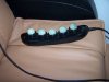
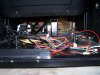
Please take some good photos of all the parts (including motors.transformers,boards etc. ) and try to make sense of what is connected to what.
We can try to work this out with you.
Then we can do some measurements and continue.
Don't ever think about "taking off every component on this board cleaning it up and re-soldering it".
That is not the way to fix stuff...probably the safest way to turn this unit into junk.
"I was going in to take out all the diodes with my soldering tool to test them and there was a bad arc from my tool to the board. Somebody had forgotten to turn off the power to the board.Some of the traces melted and there was a blown fuse. I patched up the traces and replaced the fuse.
Now the relays don't work any more with the remote. Three of them work when use the ohm meter to connect +12v to the base of the transistors. The fourth does not even though I have changed out the relay (30V coil instead of 12V coil might make that difference).
When I put my volt meter to +12V and then to the base of the transistor, I see that there is 16.7V. This does not make sense to me.
The base of the transistor that controls the non-working relay shows 14.4V.
The traces leading to these transistors come directly from the large micro controller. "
All that sounds like you are shooting a canon in a dark room.
What are the chances that I fried the controller?
Not Zero
Jona Listen,
fixing stuff is working gradually and logically.
measuring and finding the fault and then replacing the faulty part,and just that one alone!
Care to start from the begging?
and if you feel bored... take-five and don't touch
So, you don't have the schematics.
Let's try to create one the best we can:
Please take some good photos of all the parts (including motors.transformers,boards etc. ) and try to make sense of what is connected to what.
We can try to work this out with you.
Then we can do some measurements and continue.