Maker Pro
Maker Pro

Help with diagnosing problem with pcb from charge controller

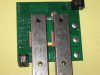
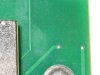
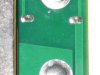
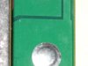
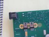
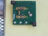
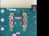
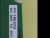
The board on the charge controller for my wind generator is not working, possibly from power surge from generator or batteries. Replacement board is not available (company went out of business). Is it possible for me to test the components on the board with just a DMM or should I try and find someone who can do it for me? Sure could use some help/guidance. Thanks.
 

davenn

Moderator
Hi
welcome to the forums :)

Its possible you may be able to do some testing :)

we need lots more info first, tho

how about some sharp and well lit pics of the circuit board, both sides
maybe do some annotations to show where the interconnecting wires to and from the board go to.

cheers
Dave
 
Here is a picture of the board contained in the instructions for the controller. The three large lugs on the left are dc input from the generator. Two wires upper left are to the dump load. White connector upper right go to the dump load switch and the led indicator lamps. At the bottom, just off picture, are the battery connections. Hope the picture is ok. Tks for your help. Tom.


Hi
welcome to the forums :)

Its possible you may be able to do some testing :)

we need lots more info first, tho

how about some sharp and well lit pics of the circuit board, both sides
maybe do some annotations to show where the interconnecting wires to and from the board go to.

cheers
Dave
 

Attachments

  • Picture.jpg
    Picture.jpg
    262.1 KB · Views: 160
Last edited by a moderator:

davenn

Moderator
hi :)

not really close enough for us to determine any faulty components
can you please take photos of both sides of the board sharp and well lit
close enough that we can see markings on components

cheers
Dave
 
hi :)

not really close enough for us to determine any faulty components
can you please take photos of both sides of the board sharp and well lit
close enough that we can see markings on components

cheers
Dave
Here are a bunch of close-ups. Thanks for trying to help. Tom.
hi :)

not really close enough for us to determine any faulty components
can you please take photos of both sides of the board sharp and well lit
close enough that we can see markings on components

cheers
Dave
 

Attachments

  • Picture 001.jpg
    Picture 001.jpg
    220.6 KB · Views: 197
  • Picture 002.jpg
    Picture 002.jpg
    130.6 KB · Views: 191
  • Picture 004.jpg
    Picture 004.jpg
    148.9 KB · Views: 178
  • Picture 005.jpg
    Picture 005.jpg
    125.1 KB · Views: 163
  • Picture 006.jpg
    Picture 006.jpg
    137.6 KB · Views: 187
  • Picture 007.jpg
    Picture 007.jpg
    144.5 KB · Views: 165
  • Picture 008.jpg
    Picture 008.jpg
    146.7 KB · Views: 199
  • Picture 009.jpg
    Picture 009.jpg
    141.7 KB · Views: 157
  • Picture 010.jpg
    Picture 010.jpg
    163.3 KB · Views: 165
  • Picture 011.jpg
    Picture 011.jpg
    177.8 KB · Views: 187
  • Picture 012.jpg
    Picture 012.jpg
    155 KB · Views: 162
  • Picture 013.jpg
    Picture 013.jpg
    156.7 KB · Views: 166
  • Picture 014.jpg
    Picture 014.jpg
    146.8 KB · Views: 153
  • Picture 015.jpg
    Picture 015.jpg
    138 KB · Views: 169
  • Picture 016.jpg
    Picture 016.jpg
    134.1 KB · Views: 163
  • Picture 017.jpg
    Picture 017.jpg
    151.9 KB · Views: 158
  • Picture 018.jpg
    Picture 018.jpg
    152.4 KB · Views: 162
  • Picture 019.jpg
    Picture 019.jpg
    149.1 KB · Views: 190
  • Picture 020.jpg
    Picture 020.jpg
    153.1 KB · Views: 175
  • Picture 022.jpg
    Picture 022.jpg
    147.7 KB · Views: 163
  • Picture 023.jpg
    Picture 023.jpg
    121.8 KB · Views: 175
  • Picture 031.jpg
    Picture 031.jpg
    110.3 KB · Views: 187
  • Picture 032.jpg
    Picture 032.jpg
    117.9 KB · Views: 164
  • Picture 033.jpg
    Picture 033.jpg
    102.1 KB · Views: 164
Has anyone had a chance to look at all the pic's I posted? Are there too many; not enough; not clear/close enough; would more info help? Really appreciate the help. Tom.
 

(*steve*)

¡sǝpodᴉʇuɐ ǝɥʇ ɹɐǝɥd
Moderator
D7 in your second image looks like it has had mechanical damage (was it hit by a nut or a spanner?). Check that.

I would also check the 6 TO-220 devices that are under the heatsinks. As the connections are exposed, you can test to see that they aren't shorted without removing the heatsinks.

You may have to remove the heatsinks to see the part numbers though.

Also, don't use a flash, it causes lots of specular highlights that can hide things.
Steve, thanks for your response. Let me give everyone a little more detail. This is a charge controller for a wind generator. The ac from the generator is converted into dc current and enters the controller via the three connectors on the left side of the board. The controlled dc current leaves via the two large lugs on the silver colored bars at the bottom. The problem occurred when I was changing out my batteries. Instruction were to disconnect at least two of the three leads from the generator before disconnecting the batteries. I believe that one of the two wires remained touching the connecting point. When I disconnected the batteries I believe that uncontrolled voltage entered the board from the generator. D7 is in the area where the voltage would have come in. As far as I can remember, no damage was done to D7. I used my multimeter (only electronic testing tool I have) to check for continuity with negative results. I do not know how to check D7 further. I am not sure what you mean by "the 6 TO-220 devices under the heatsinks." Thanks again for your help. Tom.
 

(*steve*)

¡sǝpodᴉʇuɐ ǝɥʇ ɹɐǝɥd
Moderator
Picture 1 shows the heads of 6 bolts. Between them are drawn the shape of 4 transistors that will be visible once you remove the screws and the metal covering them. There is likely to be some white or grey paste on the devices and the metal to help transfer heat.

These devices are the ones which switch the power and are also the ones likely to have been damaged. Once you expose them you should ge able to read the part numbers from them. This will allow us to tell you how to test them.

TO-220 is the name of the package. The drawing on the top side of the board is of such a device. (It's as descriptive as saying a car is a sedan or hatchback. It tells you something about the shape of the car, but nothing much else).

As for D7, if you have a diode test range on your meter, with the leads one way around you should get a low reading (perhaps 0.2 to 0.7) and a much larger value with the leads the other way around. If you don't have a diode range, then a resistance range should give a much lower reading in one direction as opposed to the other. Tell us what range you used and the readings you get.

Thanks for walking me through that. The number(s) on the back of the transistor is JRFB4410 and under that is 641P. Letters on bottom are PC and QB.
Multimeter does not have diode tester. With scale set at 200k, a reading of =
40 with positive on the left and a reading of 86 on the right. Only looked =
at one transistor, will all four be the same? After 11:00 pm here, guess it=
is time to call it a night. Thanks again for trying to help a technology c=
hallenged person. Tom.
 

KrisBlueNZ

Sadly passed away in 2015
www.irf.com/product-info/datasheets/data/irfs4410.pdf

N-channel MOSFET; 100V, 96A. RDS(on) typically 8 milliohms; maximum 10 milliohms, at VGS=10V.

Applications:
  • High Efficiency Synchronous Rectification in SMPS
  • Uninterruptible Power Supply
  • High Speed Power Switching
  • Hard Switched and High Frequency Circuits
Are they all the same?

There's probably not much point checking them individually while they're in-circuit since they'll probably be in paralled groups.
Thanks for the info. If they are in parallel and attached to the board, is there a test that I could do to determine if all are good or if one or all are bad? Limited test equipment and knowledge. Thanks. Tom.
 

KrisBlueNZ

Sadly passed away in 2015
Upload a photo showing all six of them with the metal bits removed. I will mark up the photo to show you where to measure with your multimeter.
 

KrisBlueNZ

Sadly passed away in 2015
Sorry, you're right. There are only four.

You've told us the markings on one of them. It's likely that they're all the same, but not certain. Can you check the others please.

While you have the heatsinks removed, can you take a few photos of what's underneath them (i.e. between the heatsink(s) and the board).

Can you take a photo of the whole board, rotated so it best fits the camera frame. Please read the guidelines at https://www.electronicspoint.com/resources/how-to-take-photos-of-circuit-boards.6/

Please add text to the board identifying the major connection points and listing all the markings on any component with three or more leads.
 

Attachments

  • wind gen pcb 001.jpg
    wind gen pcb 001.jpg
    106 KB · Views: 168
  • wind gen pcb 002.jpg
    wind gen pcb 002.jpg
    106.9 KB · Views: 149
  • wind gen pcb 003.jpg
    wind gen pcb 003.jpg
    95.8 KB · Views: 146
  • wind gen pcb 004.jpg
    wind gen pcb 004.jpg
    30.8 KB · Views: 139
  • wind gen pcb 005.jpg
    wind gen pcb 005.jpg
    31.5 KB · Views: 139
  • wind gen pcb 006.jpg
    wind gen pcb 006.jpg
    42.1 KB · Views: 143
  • wind gen pcb 007.jpg
    wind gen pcb 007.jpg
    38 KB · Views: 142
  • wind gen pcb 008.jpg
    wind gen pcb 008.jpg
    33.4 KB · Views: 176
  • wind gen pcb 009.jpg
    wind gen pcb 009.jpg
    20.6 KB · Views: 136

(*steve*)

¡sǝpodᴉʇuɐ ǝɥʇ ɹɐǝɥd
Moderator
That's excellent and it confirms the parts are all in parallel. That also pretty much confirms that they will be the same part number.

Note that each has its own gate driver. (also good).

Take note of this image:
11462-08a13dfbe49d6f598bfcc9e9d19b27f1.jpg


Use your multimeter on the diode test range or a low ohms range to check the resistance between the top two pins. Then swap the multimeter leads over again and get a second reading.

You only need to do this for one device because they're all connected together. The pin NOT involved at present is the one with the small track leading from it to other components.

Tell us the rang you used on your meter and the readings you obtained.

Oh, and was there any heatsink compound on the heatsinks when you removed them?
Meter was on 200 and with red lead on top reading of 90.2. When leads were reversed no reading. Did the same test on the one above with same results. Must be clear coating on pcb, had to scrape the joints a little. There was/is no compound but there is a red gasket type material under the center screw and plastic spacers on the others. The pictures were a mistake. Was trying to figure out how to put text on a picture when I pushed wrong button. Sorry bout that. Thanks Tom.
 

(*steve*)

¡sǝpodᴉʇuɐ ǝɥʇ ɹɐǝɥd
Moderator
Presumably "no reading" means "OL". If so, that's great. There is a diode across the drain and source and you have detected that. This means that none of the mosfets are shorted between drain and source (a common failure mode).

Kris did suggest you check the other mosfets for their part numbers, so perhaps you should :)
All four have the same number. Thanks. Tom
 
Top