Rick,
I would go with Edd's and Sunnysky's suggestion at this stage:
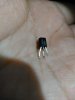
replacing the Trs from the bad channel and inserting them in the good one, after they are cleaned well(photo?).
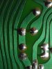
but first inspect Q601 visually for corrosion etc.
and please measure the voltages relative to Gnd on the output (junction of R646 and R648 ,if it is easier measure the voltages on both sides of R628 instead),and the voltages on Q608.Q606
Do I still leave the leg of R627 off and Q605 off the board before I swap Q603 and Q604?
")