Maker Pro
Maker Pro

Over-voltage protection for op amp

Hi all,

I would like to add an over-voltage protection resistor (Rp) for my AD549 op amp, which is occasionally subjected to 35 V at its inverting input. The op-amp is supplied +/- 5 V.

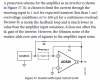
The manual indicates that Rp should be chosen to limit the current to 100 uA.

I am not quite sure how to choose the right resistor, because the op-amp itself has a significant input resistance.

Today, I tried a 1 MOhm resistor (wanted ~300 kOhm instead), but this seemed to add a few standard deviations of noise, in addition to what seemed like a drifting voltage (or slow response) at the op-amp output.

Figures:
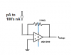
Op Amp over-voltage.png -my circuit without Rp
AD549.png -from manual

Any sugestions?
Adam
 

Attachments

  • Op Amp Over voltage.png
    Op Amp Over voltage.png
    5.5 KB · Views: 159
  • AD549.png
    AD549.png
    30.6 KB · Views: 145
You could connect your input via a resistor R1 to the anode of a diode having its cathode connected to the +ve supply. That will clamp the input to 0.6V above the supply. Diode current max=(35-5-0.6)/R1. A second resistor R2 could go between the anode and the inverting input. R2min=0.6V/100uA=60k.
 
You could connect your input via a resistor R1 to the anode of a diode having its cathode connected to the +ve supply. That will clamp the input to 0.6V above the supply. Diode current max=(35-5-0.6)/R1. A second resistor R2 could go between the anode and the inverting input. R2min=0.6V/100uA=60k.

Good solution, which I will implement; however; I need an even simpler single-resistor solution for the next two weeks or so before the diode shipment arrives.
 
The input current of an AD549 is almost nothing. Your negative feedback resistor value is very high at 5M so an extremely high value protection resistor of 300M (not 300k) is needed which creates a lot of noise.
 
Sorry, the 300k resistor value is correct and will not add much noise compared to your very noisy 5M resistor.
If an input voltage 0.6V higher than the supply is acceptable then you would think the datasheet would say so.
Instead, the datasheet says the absolute maximum allowed input voltage is equal to the supply voltage.
 

CDRIVE

Hauling 10' pipe on a Trek Shift3
Good solution, which I will implement; however; I need an even simpler single-resistor solution for the next two weeks or so before the diode shipment arrives.
Adam, if every request on EP could be resolved with a single resistor there wouldn't be much point in keeping EP up and running. There must be some scrap electronics you could cannibalize for a single common Diode?

Chris
 

(*steve*)

¡sǝpodᴉʇuɐ ǝɥʇ ɹɐǝɥd
Moderator
A diode will clamp the input voltage to be higher than the maximum allowed input voltage.

That's why you have the resistor as well (or even 2 resistors, one before the zener to limit zener current, and one after to limit input current).
 
The input has a maximum current rating because it probably already has a protection diode which has a low current rating. The protection resistor shown in the datasheet does not show an additional diode so why add one?
 

(*steve*)

¡sǝpodᴉʇuɐ ǝɥʇ ɹɐǝɥd
Moderator
The input has a maximum current rating because it probably already has a protection diode which has a low current rating. The protection resistor shown in the datasheet does not show an additional diode so why add one?

Because it allows you to use a lower value resistor (for lower noise). For logic, it will also improve speed by preventing the high series resistance from creating a significant RC delay.
 
Top