-
Categories
-
Platforms
-
Content
Please measure the voltages on Q601,Q603,Q605.
and R611, R615 all relative to GND.
Note that Q601/603 pin-out is different than Q605 :
View attachment 28274
Rick,
Q601,Q603 readings look "swapped" C and E,can you please confirm that.
Q605 readings are very strange and don't confirm the readings of Q601 and Q603.
You see, the B of Q605,C of Q601, and C of Q603 are connected together and should have the same voltage.
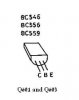
Here are the pinouts please re-measure.
View attachment 28276 View attachment 28278
Please add the measurements on : R621 and R633 and Q607 (re-measure).
Q605 E=C=44.1V ?
Can you confirm this please.
O.K disconnect the receiver from mains.
Verify there is no voltage on Q605 C,E.
In diode mode test check the resistance between C and E of Q605 and reverse the probes as well.
Do the same measurements in Resistance non-diode test mode.
What do we get(a total of 4 measurements)?
In any resistance that will show anything .
You may start high ,like 2M and if it shows lower resistance set it to a lower range.
After you have checked the above.
Please disconnect the GND wire we have connected to the leg of R627 (820ohm/2w) and leave the leg open.
Measure the voltages on Q605 and Q607.
What do we get?
Please check resistance(non-dioed mode) of
Q603 C and E to GND (with the leg of R627 lifted and not connected to anything)
What do we get?