Hi guys,
I am new to the forum. I am a chronic tinkerer in the garage and have stumbled across uncertainty regarding wiring in a single phase motor.
Background:
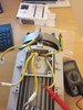
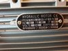
The motor is for a hydraulic scissor lift to raise vehicles. The original motor burnt out. Becuase the vehicle lift was still under warranty, I got sent a new motor. The issue is, none of the wires are labelled and they are all yellow.
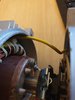
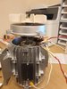
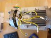
I am therefore unable to figure out wires for run winding, wires for start winding. I have opened up rotor bit of the motor and can trace one of the cetrifugal switch wires but the other one is a little more difficult to trace as it has been cable tied to the copper windings. It also means that I cannot remove the motor shaft completly as this wire is fixed.
On the old motor,
There was wiring diagram and each wire was labelled: u1, u2, z1, z2, v1 and v2.
Unfortunately, I don't have this luxury with the new motor.
I have taken some pictures. Please see below.
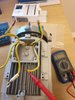
I have been testing the resistance across wires - the issues is, I cannot make any sense of the values.
If I test switch wire across to other 5 wires I get the following values:
1.6 ohms
4.1 ohms
4.1 ohms
3.3 ohms
4.1 ohms
Doing some research am I correct in thinking the following:
the 1.6 ohms is the other switch wire ?
the 3.3 ohms is probably a start wire?
Are there any other deductions I can make from this?
Remember, the only wire I am certain about, is the one I can visually trace up to the centrifugal switch.
Your help is much appreciated as this is very unhelpful wiring.
Thanks for the help.
I am new to the forum. I am a chronic tinkerer in the garage and have stumbled across uncertainty regarding wiring in a single phase motor.
Background:
The motor is for a hydraulic scissor lift to raise vehicles. The original motor burnt out. Becuase the vehicle lift was still under warranty, I got sent a new motor. The issue is, none of the wires are labelled and they are all yellow.
I am therefore unable to figure out wires for run winding, wires for start winding. I have opened up rotor bit of the motor and can trace one of the cetrifugal switch wires but the other one is a little more difficult to trace as it has been cable tied to the copper windings. It also means that I cannot remove the motor shaft completly as this wire is fixed.
On the old motor,
There was wiring diagram and each wire was labelled: u1, u2, z1, z2, v1 and v2.
Unfortunately, I don't have this luxury with the new motor.
I have taken some pictures. Please see below.
I have been testing the resistance across wires - the issues is, I cannot make any sense of the values.
If I test switch wire across to other 5 wires I get the following values:
1.6 ohms
4.1 ohms
4.1 ohms
3.3 ohms
4.1 ohms
Doing some research am I correct in thinking the following:
the 1.6 ohms is the other switch wire ?
the 3.3 ohms is probably a start wire?
Are there any other deductions I can make from this?
Remember, the only wire I am certain about, is the one I can visually trace up to the centrifugal switch.
Your help is much appreciated as this is very unhelpful wiring.
Thanks for the help.