Maker Pro
Maker Pro

measuring output current circuit ?

Put an Ohmmeter across D+ and D-to see wheter there are resistors at all - have the charger unplugged for a while before you measure to ensure there is no residual voltage on the output.
I can't find any reference describing the particular setup for the Xcharge system your phone uses.
DC-DC-9V-12V-24V-to-5V-3A-USB-step-down-voltage-regulator-module-Converter-Phone.jpg


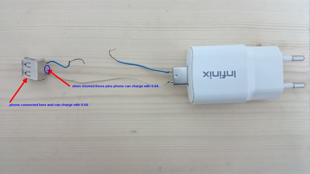
i measured across D+ and D- on the original charger and it was shorted, then i measured the drained current from the charger and it was 0.85 A.." main charger"

then i connect the module to my car cigarette plug the output for charging were 0.06 A, but when i accidentally +5v and D+ the charging current jumped to 0.48A

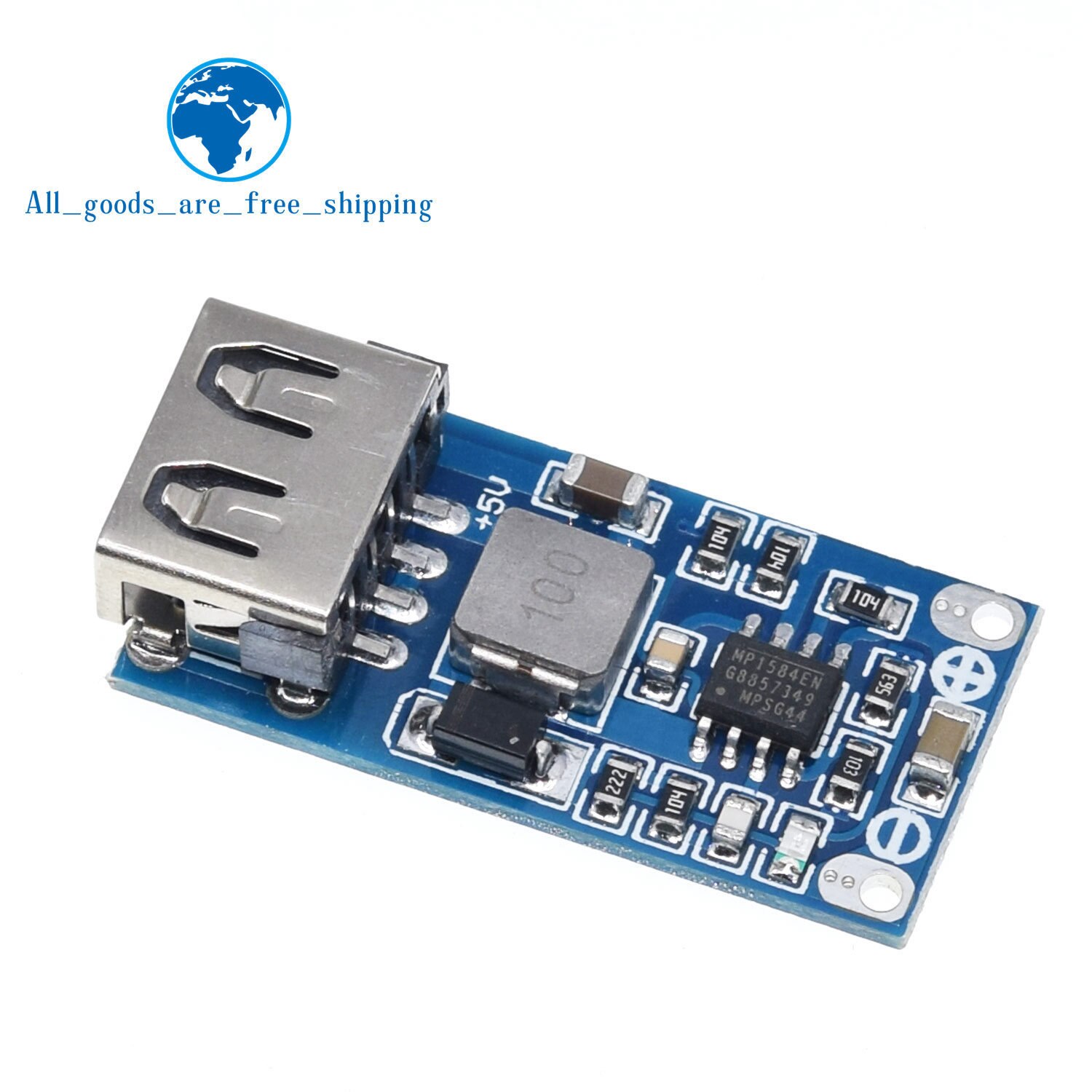
any explanation? and what can i do to make my phone drain up to 0.85A from the module , since in it's description it said "DC to DC Converter 9-28V to 5V 3A USB Step Down Power MP1584 Module"
 

Harald Kapp

Moderator
Moderator
any explanation?
The charge current is determined by the charge electronics in your phone, not the charger. The charger only needs to be able to supply the required current (compare this to an appliance connected to a mains outlet: current draw is determined by the appliance, not the outlet.). By accidentally connecting D+ and +5 V the phone will have taken this as a signal that the charger is able to deliver higher current and switched to a state where it draws more current.
i measured across D+ and D- on the original charger and it was shorted
Try shorting D- and D+ at the car charger's output terminal.
Since I lack information on the specific coding of the phone's charging system, I cannot give you better advice. You'll have to test what works for you. Or open the original charger and analyze the circuit.
 
Or open the original charger and analyze the circuit.
why would i need that since current draw is determined by the appliance?
all what i want is to figure out how to make the phone draw out of that model higher current rate.

the original charger doesn't give any voltage on the D+ , D-

to be able to measure the drain current from the main charger, i had to connect only the 5+ and GND from the main charger with eternal wires to the phone charging cable and multimeter in series on amp scale it was darning like 0.6A but when i shorter the D+ and D- on the charging cable the phone drained up to 0.8A

so on the module i shorted the D+ , D- but nothing the phone does not drain higher current, but when i shorted D+ with 5+ it drain up to 0.5A

why?
why wouldn't it drain 0.6 like in the main charger when i only connect it with 5+ and GND?
why when it have 5+ and gnd from the module it goes 0.06A not 0.6A like the main charger?

i'm just trying to understand on what base the phone charge with 0.6A or 0.06A since what i only connect to it from the main charger or the module were just 5+ and Gnd
 

Harald Kapp

Moderator
Moderator
why would i need that since current draw is determined by the appliance?
Because the coding is in the charger. The coding tells the phone the amount of current the charger is able to supply. Then the phone switches to a mode that actually draws that current.
the original charger doesn't give any voltage on the D+ , D-
But it may have resistor combinations (I linked to that topic before) that the phone can "read".

why?
why wouldn't it drain 0.6 like in the main charger when i only connect it with 5+ and GND?
why when it have 5+ and gnd from the module it goes 0.06A not 0.6A like the main charger?
As I said, I'm sorry but for lack of information this I cannot answer.


Because the coding is in the charger. The coding tells the phone the amount of current the charger is able to supply. Then the phone switches to a mode that actually draws that current.
maybe i couldn't explain what i were saying in better way..
that's the circuit i made to be able to test the current by the multimeter on the blue wire, so as you can see no D+,D-
all what t can get is 5+ and gnd unless those are what tells the phone the amount of current the charger is able to supply

and when i short the D+ and D- on the external femal USB connector the phone drain up to 0.85 A

so what exactly tell the phone how much current to dain if it was the short on the D+ and D- on the external femal USB connector, then why the same way doesn't work out on the Buck converter module
 
Top