Maker Pro
Maker Pro

Marks dog door

Ill
View attachment 26578
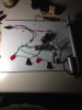
So.. I've used some other images.

Notes/Step-by-Step:
Power is connected to pin 2 on each regular relay.
Power is connected to Timer/Relay 'common' output terminal.
Power is connected to a 'Normally Open' push-button.
Other side of Normally Open push-button is connected to Timer/Relay 'Vcc'.
Battery negative is connected to Timer/Relay 'GND'.
Battery negative is connected to pin 1 *and* pin 4 on each regular relay.
Timer/Relay Vcc will also connect to a 'Normally Closed' push-button.
Other side of Normally Closed push-button is connected to Timer/Relay 'N/O' output terminal.
Timer/Relay 'N/O' output terminal is also connected to pin 8 on only one of the regular relays.
Timer/Relay 'N/C' output terminal is connected to pin 8 on the other regular relay.
Remaining pin on each regular relay goes to the actuator. (you can swap these wires to make the actuator move in the desired direction)
.

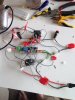
When 'Normally Open' button is pressed, power will be supplied to the Timer/Relay. The Timer/Relay will 'click' and provide itself with power through the 'yellow' wire. The button can now be released. The Timer/Relay will also provide power to one of the regular relays which will reverse the power to the actuator causing it to move.
When the Timer expires, the Timer/Relay will unlatch and will remove power to itself & the regular relay. Power will then flow into the other regular relay through the blue wire and provide power to the actuator in the 'normal' direction.
The 'Normally Closed' button is an 'over-ride' ... if you want to cancel opening the door, or need to close it before the timer expires, this button will forcibly turn the timer off and cause the door to begin closing.
** There are simpler methods to do this, but this particular method is built so that at any point in the future you can add-on or alter the circuit incredibly easily. Additional 'safety' sensors or switches can be easily connected at a later date if you feel they should be used.

How does this look to you? If you need any clarification, please let me know.
 
Hi again - I think we are close to a win - I have put circuit together - when you plug in the power the circuit makes the actuator run out to its full length but you don't need to push the normally open button to start the process if you press the no button it cuts the power ??
 

Attachments

  • image.jpeg
    image.jpeg
    132 KB · Views: 100
Hi again - I think we are close to a win - I have put circuit together - when you plug in the power the circuit makes the actuator run out to its full length but you don't need to push the normally open button to start the process if you press the no button it cuts the power ??
Just confirming that the NC button is on the right in that image, and the NO button is on the left?
Once we have the function working properly, we can simply swap the pins on the actuator to reverse it's motion.
It should not be possible to 'cut power' to the actuator with this particular layout... The middle output pin on the timer/relay will always be live, and one of the regular relays will always be activated.
The NC button should sit between the feedback loop of the Timer/Relay... the NO output pin, and the power input pin. It's only job is to interrupt the current 'opening motion' and make it begin to close again when pressed once.
The NO button should sit between power and the Timer/Relay power input and is only there to be the initial trigger to activate the timer.. the loop mentioned previously will hold the timer/relay on once you release that button.
Other than that, there should be nothing except maybe a fuse, or future 'safety' or 'limit' switches inbetween the power and the normal relays or actuator.
Perhaps you have accidentally swapped the NO and NC outputs of the timer/relay?

(It's hard for me to confirm.. as the wires in your image are hard to follow.)
 
Hi gryd 3 - I have checked the circuit and replaced the relays with easier to use ones and I am still getting the same result as before mentioned - I've triple checked the circuit and it seems correct to your design - I've checked the no and nc buttons are as required - not sure what to try or check ??
 

Attachments

  • image.jpeg
    image.jpeg
    285.6 KB · Views: 72
Hi gryd 3 - I have checked the circuit and replaced the relays with easier to use ones and I am still getting the same result as before mentioned - I've triple checked the circuit and it seems correct to your design - I've checked the no and nc buttons are as required - not sure what to try or check ??
It is so incredibly difficult to follow the wires there :S
Behaviour *should* be:
- Plug in. Actuator will immediately begin to move to it's *resting* position. (If it begins to 'open' simply swap the red/black wires of the actuator.)
- Once the Actuator moves to it's resting limit, it should stop and stay there indefinitely.
- Press the 'Open' button, which sis connected to Timer/Relay 'VCC' and Power. You should hear a click and the actuator will begin to move. You can let go of the button and the actuator should continue to move.
- Hit the other button now, and you should hear another click of the relays and the actuator will begin to move toward it's *resting* position again.


Can you please tell me exactly how it is behaving now? Which step fails?
Don't worry about which direction the actuator moves... you can change that simply by swapping it's red/black wire.
I'm more interested in making sure the actuator *always* moves. Pressing either button should not result in the actuator stopping half-way.
 
Plug in /actuator is at rest /press no button and I hear the relay click /but no actuator movement
This sounds proper depending on where the actuator currently sits. Remember it will move toward it's current wired *resting* position.. If it's already at the end of it's travel this is correct.
Pressing the 'Open' button once, should make it begin to move, and if you leave the circuit be, it should automatically reverse direction after the timer expires.
for some reason I feel the problem might be in the timer the led light in the timer never comes on
We didn't really play with the timer/relay at all, so we can't say if it works as desired yet.
If you completely disconnect the 'output' pins on the timer relay then plug the unit in, you should *not* hear any relay click. The click you heard before should have been one of the normal relays and is normal.
 
When I unplugged the green out put on the timer relay and the pressed and held the no button the actuator motor ran when u release the no button the actuator stops----- when the green timer relay output is plugged in and I push and hold the no button and at the same time turn the small screw on the blue component of the timer the actuator extends
 
When I unplugged the green out put on the timer relay and the pressed and held the no button the actuator motor ran when u release the no button the actuator stops----- when the green timer relay output is plugged in and I push and hold the no button and at the same time turn the small screw on the blue component of the timer the actuator extends
Adjusting the screw on the blue component will adjust the delay of the Timer.
You should be able to set this to a long duration and forget about it. If the timer is set to a very small duration you may not notice it changing twice.
When you removed the output connector of the timer and pressed the NO button... did the actuator extend or retract? You said it moves but didn't say which direction.
 
I have turned the timer screw on the blue component and currently the actuator will extend all the way with one touch of the no button but it does not retract unless you push the nc button
 
When the timer relay is in plugged and you push no button the actuator extends but only while you keep the no button closed
Then the Timer/Relay would appear to be set for a very very small duration.

The NO button, and NO contact on the output of the Timer are in parallel.
Both items primarily supply power to the Timer/Relay, and will additionally supply power to trigger one of the regular relays.
If the the build only extends the actuator while the NO button is pressed, then the Timer/Relay may be set to time that is MUCH too small, or the Timer/Relay may be defective.

I would suggest the following:
- Remove the output green terminal and set aside.
- Disconnect the Ground and VCC wires from the input of the Timer/Relay and set aside.
- Directly power the Timer/Relay *only* with your power supply and listen for a relay click or watch for an LED indicator.
- Listen for a relay click... it *should* click immediately to turn itself *on* ... then after a delay, click once more.
- It *may not* click immediately... in which case, please leave it connected and wait... you may have to wait a couple minutes... but wait and listen for a click or for a status LED to change.

*If you have a multi-meter that can measure resistance, you can use it to measure the middle output pin, and the clockwise adjacent pin next to it. (The icon will show nothing connected to this pin)
It should read infinate or 0L Ω ... The middle pin and counter-clockwise adjacent ping would read 0Ω.
If you hear a click, re-measure, these values should change when the relay is *toggled*

It most certainly sounds like the Timer/Relay component is the current road-block...
However... If you let go of the NO button, does the actuator retract? (Remember , it should not simply sit still... it will always retract or extend)
 
Top