I've missed some of your posts, sorry!
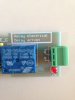
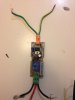
The diagram I posted earlier shows a + and - indicator on the 'coil' of one of the relays.
This is your timer relay.. Just make sure the gnd is on the negative battery terminal.
The pos, will be connected to the buttons shown in the diagram.
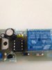
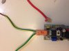
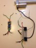
Take a look at the little diagram on the green connector on your timer relay.
There are 3 pcs. The top and bottom pin go to a line with a 90 degree bend in it to a circle.
The middle pin goes to a 'bent' line that is angled.
This middle pin is the 'common' contact. The icon indicates that it's normally connected to the top pin. When the relay triggers, the middle pin will disconnect from the top and connect to the bottom. This is the behaviour we are taking advantage of to forward/reverse the actuator. (But we needed the other relays to reverse the current... because a single switch won't do it.)
Please keep in mind that the diagram I posted is operating on the assumption that the relay *immediately triggers* once power is received... then after the delay , turns back off.
This relay could also remain off for the duration of the timer before turning 'on' .
I don't recall reading the type of operation, nor have you stated if you have tested it.
We can adjust the circuit easily afterward if this is the case, but I still suggest testing first
")