Maker Pro
Maker Pro

Marks dog door

Hi I am electronically illiterate so you might have to go slow on me please . My project requires a 12 v circuit design please .
The idea is to open and close small dog door with a 12v 3 amp actuator
The actuator takes 40 seconds extend and 40 seconds to retract. I hoping to be able to push a switch / button which will connect to your circuit suggestion which will extend the actuator rod and to its full length Which takes 40 secs then retract the actuator rod without pushing the switch / button a second time ? Your help would be much appreciated . Thanks Marks dog door.
The circuit will work, But 40 seconds may as well be forever as far as a dog is concerned! ours go in and out in less than a second! I suggest you use a lever to open the door, a very long lever on the door side and a very short lever connected to the actuator rod. Then set the limit switches so the actuator stops when door is open.
 
Hi Kaj Your idea would work for sure but now I'm involved with Gryd 3 idea I'm enjoying the learning process and hope to put his plan to completion Thankyou for your interest Mark
 
Hi gryd3 the timer has arrived I think it's what we are looking for - Marks dog door
We can make this work.
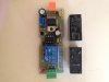
The output is a single pole, double throw relay.. so it has a common pin, a normally closed and normally open pin.
I do not see a 'trigger' input anywhere on that device though which has me a tad concerned... it almost seems like the timer 'starts' when you provide power to it, and when the timer is up the relay goes back to neutral.
If this is the case, we can make the timer-relay power itself, so you can trigger it with a momentary push-button ;)

I would also suggest the additional following parts:
- Two more relays. Just simple Single-Pole, Double-Throw relays that you can get at an automotive store, hobby store etc... 12V, and considering your actuator takes up to 3A, I'd find a relay sized at least 5A for this application.
(These relays will be used in a type of H-bridge that will allow the motor to reverse... if you don't want these, you will need two 12V supplies... so that you can toggle the -12V supply to the actuator with your timer relay. I recommend the additional pair of relays)
- Two normally closed, momentary push-buttons (Or microswitches) for the external limit switches. (If the actuator has two built-in, these will not be needed. You may only need one of these if you wish to use the built-in limit switch. Please confirm the use of the built-in switch first!)
- One normally open momentary push-button for the 'Door Open' trigger.
- *Optional but recommended, One normally closed momentary puch-button for the 'Door Close' over-ride.


Current plan:
The timer+relay combo will be wired so that the output of it's built-in relay will also provide power to itself. The momentary 'Open' button will cause the timer+relay combo to start and 'latch' on allowing you to release the button and the timer will continue on it's own. At the end of the timer duration the relay will return to the neutral position disconnecting power to it's timer circuit.
The 'Close' over-ride button will simply disconnect power from the relay+timer forcing it off sooner than the timer.
From here, we also connect a limit switch to each of the NC and NO outputs of the timer+relay combo. These switches will interrupt the signal from the timer if the door travels too far. ( Or to the pre-set position you would like to have )
These limit switches will then connect to their own relay.
The additional two relays will be wired such that when the timer is 'on' the relays will provide forward current opening the door. (until the limit switch is pressed, then the output will be neutral) . When the timer is off, the additional relays will provide reverse current to the actuator until the 'closed' limit switch is depressed.

This setup will allow you to use almost any device to open/close the door. A DC motor with a string, an actuator, etc... the H-bridge and limit switches will be quite robust and will also allow you to custom set the exact close and open position of the door simply by moving the limit switches.
Additional safety devices can be added and connected in series with the limit switches if you want to prevent the door from closing while something is in the door-way for example... a simple optical break-beam sensor can be installed and added on with no additional hardware. The switches and sensors will also be controlling a relay which is low-current as opposed to directly controlling the 3A actuator.

Anyway. Let me know what you think, and please confirm the exact behaviour of the motor and actuator to make sure this plan will work. (I'll draw a diagram shortly thereafter)
 
Hi again thanks for your time - it sounds good - the motor extends the actuator to its full length (which is what I need) then stops and disconnects itself from the power (I think this is what you mention as open ended) then if you swap the red and black motor wires to the opposite battery terminals it withdraws the actuator to its fully closed position (also the position I need ) then rests or disconnects itself from the power supply - mark
 
Hi again thanks for your time - it sounds good - the motor extends the actuator to its full length (which is what I need) then stops and disconnects itself from the power (I think this is what you mention as open ended) then if you swap the red and black motor wires to the opposite battery terminals it withdraws the actuator to its fully closed position (also the position I need ) then rests or disconnects itself from the power supply - mark
It sounds like it has a limit switch on both ends of travel, that is great considering the description made it sound like there was only one limit switch inside...
The parts list above is still viable, but you can dismiss the two external limit switches.
The two additional double-throw relays to make a type of H-bridge, and the 'open' and 'close' button are all that's needed to complete the project as long as the assumed behaviour of the timer+relay combo you have is what I expected.

There are only 5 terminals on it correct?
Input : Power, Ground.
Output : NC, Common, NO
(There are jumpers to adjust control voltage, and timer if I recall correctly)

The additional relays will be wired very similar to this :
locks_3_wire.gif

Black and Light Blue will be the Actuator Wires.
Alarm Lock, and Alarm Unlock will be connected to the N.O. and N.C. outputs of your timer relay.

If you don't want to use two relays like above, you can buy a single double-pole, double-throw relay which will take care of the forward and reverse motion with only the N.O. output of your timer+relay combo.


*Edit: you must be SURE that the actuator disconnects itself from power if it's all the way open or closed and not simply 'stuck' at the end of travel. This circuit will 'hold' the actuator open or closed and if it does not remove itself from power you can burn it out! (In which case, we can just add external limit switches)
 
I've up loaded a picture of timer and relays relay s only have 5 connecting points each
Excellent!
Untitled.png
The above is the additional relays you have.

Below is the schematic which should do what you want.*
*As long as the timer+relay combo 'triggers' immediately on power, then holds for the duration of the timer.
The assumption here is as follows. "Power to the timer, Relay triggers immediately, timer expires, relay returns to neutral position" If this is not the behaviour, we will need to make a slight adjustment to the circuit.

schemeit-project.png
 
And dumb question where it says 12 v all 3 wire to the same battery terminal ?
Yessir. All 12V together, and the downward arrow is the negative terminal. Those all all together too.
This was my way of trying to keep the drawing cleaner.
Sorry also - s1 switch starts the process - but I'm not sure what s2 is for ?
S1 starts the process, and the timerRelay latches which continues the process.
S2 is a 'stop and close right now' button. In case you hit open accidentally, or don't want to wait for the full duration. It works by interrupting the the timerRelay... remember it latches by powering itself, so this button will cut that connection and power it down.
 
Top