Hi again. See attached my version of your oscillator which does work. Simulated using Simetrix.
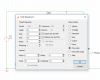
To actually make this sort of simulation work, you often need a perturbation of some sort to initiate oscillation. That is what the extra bits "V2 and C5" are for. They combine to give a very short pulse at the junction of C3 and L1. To set the pulse from V2, right click it and then set up as in the third attachment "Set V2".png.
To get best sine wave resolution, click on "Simulator" on the menu bar, make sure "Transient" is selected, click on "Advanced Options" at the bottom of the window the in the next window, set "Max Time Step" to 50p then close that window.
Now simulate and you should get the same results as me.