Maker Pro
Maker Pro

Harman/Kardon HK6500. Loudness not working when button is pressed

Amp turns on and all 4 speaker channels work, the only problem is when you press the loudness button, instead of the sound getting louder, it just shuts off the sound completely. I was wondering what components on the board have to be checked and how, if someone can help. ThanksDSCN0203.JPGDSCN0211.JPG
 

KrisBlueNZ

Sadly passed away in 2015
I guess the problem will be in the loudness circuit. Here's the schematic of it:

hk loudness circuit.png
The left and right audio signals enter on the left and are switched by SW6. In the position shown, the signals go straight through; in the other position, the loudness circuit is switched in.

The first thing to check would be the positive and negative power rails - the lines that run across the top and bottom of each circuit. The proper voltages are not shown on the diagram but they should be at least +12V and -12V. Also have a general look over that board for obvious problems.
 
Ok thanks! Not sure how to check the positive and negative rails, but I'm gonna look under the board and see if anythings under there looks like a problem
 

KrisBlueNZ

Sadly passed away in 2015
OK, I've marked the positive and negative rails in red and blue respectively.

hk loudness circuit.png
To find the positive rail on the board, look for any of the componetns that are connected to it on the schematic - R929, R937, R941, R930, R938 and R942 - and look under the board for a track that connects them together. This will be the positive rail.

For the negative rail, it's simpler - find Q911 or Q912 and look under the board to see which two pins are connected together. This will be the negative rail.

Measure the voltages on those rails with your other multimeter probe on the circuit's 0V rail. The 0V rail will probably be connected to the metal chassis, but you can also get it on the outer metal part any of the RCA phono sockets on the back panel.
 

KrisBlueNZ

Sadly passed away in 2015
OK, find R954 on that circuit board and measure the voltage at each end, with your black meter probe still connected to the 0V rail (chassis or outer metal of the RCA connectors).

Also tell me whether it is getting hot. (Touch it quickly at first - it could be very hot, and you don't want to burn yourself!)

hk R954 position.png
 
Not sure if its a separate problem but on the main board Q427 Q423 Q425 Q421 Q422 Q426 Q424 and Q428 are really hot and the board is dark around them
 

KrisBlueNZ

Sadly passed away in 2015
That's definitely a bad sign! But let's investigate the other problem first, because a missing supply rail could cause the other problem.

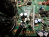
Can you find Q519 and Q520? They are probably power transistors and they may be mounted on heatsinks. I don't know which board they're on - the diagrams in the manual are poor quality scans.

If you can find them, measure the voltages on all three pins of each. Looking at the front side with the markings, with the leads going downwards into the PCB, the leads are base, collector, emitter, from left to right.

Be super careful not to let the probe slip and short the pins together because that could do some big damage. If possible, probe the pads on the bottom of the circuit board.
 
Those are it in the middle of the photo. I might have to go under the amp to get a reading because its tight. Lucky there is a bottom cover i can remove. So i use the same 0V rail?
 

KrisBlueNZ

Sadly passed away in 2015
Yes, always measure relative to the 0V rail unless you're measuring "between" two specified points.

What is that 4-pin connector with the wire pulled out of it? And the other connector, is the wire properly seated in it?
 
Sorry, that 4 pin had wires that connected to board with the loudness button. I had took that photo when I was inspecting the board when I had it all disconnected. But yes, its connected and that other set next to is seated properly.

Q520 reads
B = 1.61V
C = 0.95V
E = 0.94V

Q519 reads
B = 1 .
C = 1 .
E = 1 .
 

KrisBlueNZ

Sadly passed away in 2015
OK, those "1." indications are because the voltage is too high for the range you selected. If you see that indication, you need to use a higher voltage range. Just for future reference.

OK, there's no significant voltage on Q520. The voltages you listed for Q520 are negative voltages, right? It's important that you use the negative sign if the voltage is negative.

Can you measure the voltage at both ends of R556. It should be near Q520. If there's a high negative voltage at one end, but not at the other, R556 is faulty or damaged, so can you take a photo of it and some of the surrounding area so I know what type of component to recommend as a replacement. Also can you add your location to your profile so I know what suppliers to recommend.
 
Thanks, im learning more as I go lol. Q520's readings were all negative.

R556 read - 0.95v on one end and - 0.67v on the other end of it.

After testing R556, I disconnected those two sets of 4 pin wires to take a photo, so DSCN0224.JPG that's R556 between those 4 capacitors, its the green one.
 

KrisBlueNZ

Sadly passed away in 2015
OK, it looks like the whole negative rail is missing. Can you find C4 and C5? These will be huge cylindrical electrolytics. I think they're the big black things at the left of the last pic you posted.

Can you measure the positive terminal of C4. It should be around 40~50V positive. Then the negative terminal of C5. It should be around -40~50V.

If the negative voltage is not there on C5, trace the connection from there to D1, which is a four-terminal black device that's probably mounted to a heatsink. See if there's negative voltage there. If not, D1 is probably stuffed.

If the negative voltage is present on C5, trace it through to R556. There should be a copper path on the circuit board.

There are a number of discoloured areas on the underside of the circuit board. What components do these correspond to? Have a close look at the solder on these connections to see if it has become a "dry joint". Can you upload a close-up of the worst one?
 
Top