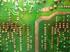
Ok. C4 and C5 actually have 4 pins each. The forth pin on both capacitors aren't soldered on the board, but I read the voltage of them anyway.
I don't see any writing on the board that tells me what capacitor is C4 or C5, but one capacitors pins read -0.00v, 0.01v, 1 .v and the forth unsoldered pin 0.02v
The other capacitor pins read -0.00v, -0.20v, -1 .v and the forth unsoldered pin -0.72v
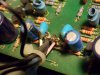
From left to right, D1 pins read
1 .v, -0.01v, -0.01v, and -1 .v
Is D1bad? and is it called an Inline Bridge Rectifier ?
How is D1 causing the loudness not to work?