KrisBlueNZ
Sadly passed away in 2015
R557 and R558 will be fine. C532 and C530 won't be damaged but you can replace them if you want, to keep everything looking the same.
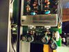
Yes, Q520 is a PNP and Q519 is an NPN. These are the two that are bolted to the heatsink, right? They are called "TO-220" packages. There will be some kind of insulating shim between each transistor and the heatsink, and there will be plastic collars around the screws that hold them to the heatsink as well. You have to keep these and refit them. If the insulating shims are made from a thin fragile glass-like sheet called mica, they may be damaged, so you might want to remove the old transistors first and check, and/or just get some spares anyway. Ask for mica insulating washers for TO-220 packages.
All of the transistors I listed are suitable. They are listed roughly in order of increasing cost. The last two on each list are actually "Darlington" transistors, which are a bit different from normal transistors, but they're equally suitable. I just mention this because the person at the store may query it.
If the shop has them, you could also pick up some replacements for Q907 and Q908 in case they are damaged too:
Q907 PNP --> MPSA56, BC640, BC327
Q908 NPN --> MPSA06, BC639, BC337.