Maker Pro
Maker Pro

Condenser dryer main board power fault

'(Give those Cap/Voltage ratings . . . along with the two that are near the LNK cluster.
Of course, the other YELLOW markups are being the LNK and the 817 optical isolator for regulation feedback.'

C11 10uF 50v

C13 47uF 50v

C10 & C15 both MCO 210
 
I came across this in a Technical Sheet for a LNK304GN, which illustrates where the 12v is derived from.

So its questionable whether the replacement LNK364PN, in my case, is actually working, or what might be preventing it from operating.
 

Attachments

  • Screenshot_20181209-205207.jpg
    Screenshot_20181209-205207.jpg
    155.5 KB · Views: 13
Having got this far I am of the belief that the uC Atmega16L is either at fault or causing the shutdown, though I'm no expert by any means and hope to be proved wrong.

Thanks again for the help! Shall plod on and report back any new findings.

I would imagine the uC "program' is locked to prevent unauthorized access which would include flags setting the BOD which probably isn't cleared by an external reset. But this is getting beyond my knowledge and possibly not cost effective for a one off project to buy interface equip etc...
 
Last edited:
I replaced it earlier just to be sure it wasn't a faulty one but results are still the same.

Could be cheapos with specs not as good as other makes or a faulty batch.

Its not running excessively hot, infrared thermo reads about 2 degrees increase.

Whereas the Atmega has next to no temp rise compared to the relay coil solder tabs which have about a 3-4degree increase (these are the relays that are directly fed from the 14v and sat waiting to be switched on via the uC).
 
Last edited:
Yikes, 6% under voltage is pretty bad tolerance there.
Sorry I can't help with the Atmega μc.
Perhaps you can manipulate inputs to see if its functioning? Even if your locked out of the μc, you should be getting some lights or something now that your DC rail is restored?
 
From what I can see its pretty much the uC that controls everythingelse after the 7805. So sadly I would say its either fried or 'lockedout'.
 
From what I can see its pretty much the uC that controls everythingelse after the 7805. So sadly I would say its either fried or 'lockedout'.
That sucks. I hate it when you invest time and parts, only to be stopped by something like this.
Perhaps one of our more knowledgeable members will chime in here.
You might want to start another thread under microcontrollers section and ask if there's a back door way of resetting it?
 
Unfortunately I think it needs to be removed from the board and the kit to clear the flags would be too costly for a one-off! Also guessing it has proprietary software that will be 'read' protected.
 
What about the programer? Do you have power there? Perhaps it can be programmed in a way the μc will respond?
Any external parts necessary for the μc to work such an oscillator circuit?
 
Nothing connected to XTAL1 or XTAL2 so uses its internal oscillator.

'Programmer', not sure what you are referring to there, please clarify. Unless your referring to the programme control dial, in which case yes it has power to it and the 'diagnostic test mode' does nothing. Not sure if there are any other dial setting procedures that will do resets etc...

Diagnostic mode - select programme dial to 'Delicates' and power on whilst holding in 'buzzer cancel' button, after 5 secs or so ALL the lights will flash, release the 'buzzer cancel' button.
Press 'start' button to go through the various cycles i.e drum clockwise no heat, then with heat, drum anticlockwise no heat, then with heat etc..

Not sure if this procedure forces a 'Reset' or not.

Presumably the reset at normal power on or a forced reset happens so quickly nS that a normal dmm would not see it happening so pointless trying. But I do know the 4.97v lingers for 2-3 secs after power down before dropping out and powering it back on quickly either just before or at the moment of 0v it appears to do nothing.
 
Last edited:
Sir notallbad . . . . .

Your last few add ons info, made me have to slightly re edit this entry . . .so as to be all encompassing . . . so here goes.
(Just now also saw that you added on, your having used BEKO's diagnostic code procedure)
You should now be OK on that U4 regs 5V output, so read past that info submitted verifying it.
But do catch all of the info on the the principal, higher 16V , being used for the 12 VDC supply for the mechanical relays driver coils.

Consulting my post #14's center photo note the 2 electrolytics around the LNK and also the two at the bottom center of the board.
They have been continually working, 25 hrs a day, in "burst" mode since the dryer was plugged into the power outlet, and being
even more taxed , at the times when the unit was operating.
If you have ripple upon them from evolved onset of ESR, that could account for the 4.7V . . .particularly if even tested unloaded.
The middle cap sets are for the in and out filters of the U4 5V reg.
So If you have no means of testing ESR, sub in some new or known good units.
Or if the unit has been running an hour or so, you can put
a fingertip at the bare metal cap top of a unit. A warm or hot one would signify a high ESR unit. If you happen to have or can access
a laser temp pistol, so much more the better in precise reading of temp differences .

((( I sees that you GOTS yerselfs . . . . a laser beam temp gun ! )))

Since you now have established the principal 16 VDC voltage that the power supply puts out and then reduces for the 5VC supply,
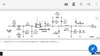
lets go to the top photo and track it. I see it originating at the right bottom corner of the LNK YELLOW BOX enclosure and traveling
up to the point where it widens and continues, but part of it branches off to feed its input to the bottom input term of U4. It also continues
up and branches off to go to the right on another feed at a 2 o clock position from U4 . It gets small and congested and I loose it.
Lastly it moves up and has to veer off to the left, 45 deg, to work around a cluster of 6 disrete parts. Then it slants 45 deg to the right and
then starts a course to the right to finally drop down to a pad of what I think being is one coil connection of the mechanical relay RL5.
Now of that cluster of two SM diodes, two metal SM resistors and two SM ceramic capacitors, I see NO additional relay driver transistor
for that RL5 ?
Looking at the affected central "light reflection" area, I do see, all lined up, 4 damping diodes for relay coils, with their driver transistors
just below them, so they must be for RL1-2-3 and 4's coils.
I do see a like arrangement of a single damping diode and driver transistor over to the right and a TACT pushbutton switch on EITHER side.
Could this be the remoted position of the RL5 driver circuitry, and are the pushbuttons being the units power on and off buttons ?
Also, I see some ancillary discrete RL5 components around its AC switching contacts . There are two series resistors, maybe like 10 ohms
that then thet tie into an anode of an unidirectional breakdown diode? . . . . possibly . . .that series combo, creating a snubber function ?

PLUS there is also another questionable electrolytic function ( What is being its capacitance + voltage r ating ? ) , that is being located near
the bottom left corner of the RL5 relay.

Are all of the relays solder connections, well flowed and looking goooooooooooood, and having no solder fracturing ?

Now in your wondering about the system U/Processor . . . I would be wanting to get ADEQUATE lengths of some multiple CAT 5 wires,
to use for hook up wire , to be able to solder tack one common wire to the shared emitter /grounds of all of the 4 relay driver transistors.
Then 1 wire each gets solder tacked to each of the 4 bases of the driver transistors,. then you remote out all of the leads other ends to get taped
onto a piece of cardboard and labeled.
THAT would THEN let you put the machines system all back together again for dynamic testing and go to the cardboard have one DC voltage
meter lead to the transistors shared ground. Then you can pick out driver transistors bases to monitor with the + meter lead to see IF and for what
duration ACTIVE HIGH LEVELS come into that base of a transistor to drive it and actuate its relay.
Thus validating, that there IS being U/Processor action.

Then you proceed as shown below . . . . to find out ?

See if this referenced procedure below is being applicable to your BEKO unit, as its very first test action MIGHT be resettting the system U/P .
Then . . . . . you can see that amongst the very first system tests, is being a validatuion of the buzzer and all of the LED's
validating their functionality, by their flashing at warp speed.

THEN you COULD fast forward testing by immediately speeding thru all of the heating modes, to get to its 7th? or 8th? test where the LEDS will
then again uber flash, at that speedy rate, and then the last push turns off the machine.


73's de Edd . . . . .
. . . . . . . . . . .


Now, I am proofreading all of this, being ever careful, so as to be sure and see if I have any words out.

 
C11 10uF 50v certainly running hotter than others if memory serves me correctly, shall check to confirm. But in any case think it probably better to just replace the elec caps.

I do have an esr meter and a cap meter which in testing the caps out of cct showed nothing obvious. I have had bad caps that tested ok in previous projects. Usually find fluctuating voltages.

C18 to the right of RL5 100uF 16v

Relay solder connections all appear good.

Yes, thats the procedure I'm using but no joy. No buzzer, no light, nothing!
I shall see about wiring it up as you suggest.

Shall trace through and get back to you regarding the remainder of your post.

Diode & transistor between the two momentary switches are for RL2.
Then from left to right of the 4 pairs of diodes and transistors immediately next to SW3 (the one on the right), RL3, RL1, RL4 then RL5.

Trace to RL5 coil from U4 is direct.
Where the trace T's off it runs under 3 x zero ohm jumper links, and connects to the right solder tab of each of the last 3 diodes to the right and also to the right solder tab on the diode thats placed between the momentary buttons to RL2.

Thanks again!
 
Last edited:
..Unless your referring to the programme control dial, in which case yes it has power to it.
Yes, thats not what I was referring to.
Just a thought, but there's a possibility that the "delicates" mode on the dial or push button inputs are not making their way back to the processor. A missing common/ground wire can stop the whole thing from working.

The caps 73's de Edd was referring to may be a non-issue at this point because you mentioned (#31) you have 4.97v and not 4.7v originally thought.

BTW, Great advice to solder the test point wires to cardboard for easy reference and labeling.
 
Get a slight fluctuating reading on the transistors of about 100mv from power up and the same on power up into diagnostic mode and selecting the various test modes.

The relay transistors are 1F7, 1FW22 and 3FW22.


What is the 'programmer' you were referring to? Via UART?
 
Top