Ok, here are some photos of a couple of quick builds.
I'll begin by showing you photos of the circuit that
works. This circuit uses a diode and variable resistor to hit a 50% duty cycle.
I'm hoping the success of this circuit will reduce concerns about long wires, solderless breadboards, etc.
View attachment 26354
View attachment 26355
View attachment 26357
View attachment 26358
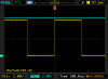
And here are some traces from the circuit that works:
View attachment 26360
Note that the duty cycle is just about 50%. I can tune it exactly to 50% if I want using the variable resistor.
Next I'll add Vcc in blue:
View attachment 26361
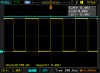
Notice that the output spikes to Vcc, but then drops below it. Let's zoom in a thousand times (from 100us to 100ns per division):
View attachment 26363
There's a small transient on Vcc (blue), but it's short-lived. The output (yellow) rises to Vcc, but then falls and stays about a half volt below Vcc for the remainder of the high phase of the square wave.
Now, let's look at the circuit that
fails:
View attachment 26365
View attachment 26366
View attachment 26368
View attachment 26369
The black cylinder is a 470uF bypass capacitor. It smooths the Vcc transient, but doesn't fix the duty cycle problem.
Here are the scope traces:
View attachment 26370
Note that the duty cycle is closer to 60% than 50%. This is the problem I'm trying to solve.
Also note the same rise to Vcc as in the working circuit, but now it falls over 1V and stays below 8V for the rest of the high phase of the square wave.
View attachment 26371
Zooming in again, we see a small transient on Vcc (blue), with a longer lived transient on the output (yellow). These aren't a major concern unless they are somehow causing the real problem.
The real problem is that the output then drops below 8V and stays there for the remainder of the high phase.
View attachment 26372
The above image shows the output in yellow and the capacitor charge (pin 2) in blue. The rising and falling edges occur when the charge on the capacitor hits 3V and 6V respectively, as expected.
However, the capacitor charges more slowly than it discharges because the output is below 8V rather than at 9V.
Unless there's a way to get the output to generate a solid 9V signal, I don't see how this circuit can possibly generate a 50% duty cycle signal.
I tried switching my probes from 1x to 10x and saw no real difference. As you can see in the first photo, my probes' grounding leads are short. I also tried turning on bandwidth limiting on the scope and the traces barely change shape. And I've measured clean square waves from other sources at similar frequencies. I'm confident my 100 MHz scope is accurately measuring the voltages in the circuit.
")