Maker Pro
Maker Pro

Capacitor Knowledge Wanted

I'm repairing The Glorious Deathmobile Mark II's amplifier (pulled from a '96 SHO), and TLDR needs new caps.

Now, There's a bunch of ceramic discs simply labeled "220" with a small dot underneath the number. I assume that's 220pf, but any other spec is a mystery to me. I'd like to replace them with something a little more "audiophile", and although I've found a bunch of info online, nothing is leading me to a definite replacement for this exact cap/application.
Also, a few of these caps bridge the + and - sides of the audio, on both the input and the output of the amp IC. Would these be the coupling caps?

Another issue...when I tested some of the larger Electrolytic caps with my cap meter, I was getting wildly unsteady readings. Everytime I put the probes to it (removed from the circuit) I got a completely random number. What's up with that?
 

Harald Kapp

Moderator
Moderator
Everytime I put the probes to it (removed from the circuit) I got a completely random number. What's up with that?
Old electrolytic capacitors tend to loose electrolyte and therefore capacity. They no longer work as intended and capacitance can vary e.g. depending on where electrolyte is available at the moment you measure. Replace those by new ones with same capacity and same or higher voltage rating.
I assume that's 220pf, but any other spec is a mystery to me.
See e.g. here. Any other rating (voltage, accuracy) is usually either printed on the capacitor or you'd have to find the datasheet for the capacitor in question. I can't help with the dot, whether it is signifant or not.
Ceramic capacitors are lebeld in pF. 220 is 22 × 100 = 22 pFUsually there is no need to replace ceramic capacitors unless visually destructed.
 

(*steve*)

¡sǝpodᴉʇuɐ ǝɥʇ ɹɐǝɥd
Moderator
Please post a photo of the capacitors. It's generally reasonable to assume that electrolytics need replacement in old equipment, but there are some capacitors which don't need replacing. Ceramic, film, and Mica capacitors will generally stand the test of time.
 
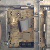
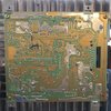
The caps in question. Some of the ceramics are physically broken, hence the need....

...or not. The website is giving me an error for each pic I try to upload
 

(*steve*)

¡sǝpodᴉʇuɐ ǝɥʇ ɹɐǝɥd
Moderator
Use an image compression tool (I use LitPhoto on my phone) to reduce the side of the images. I set the quality to 80% which reduces the size of the file dramatically.
 

Harald Kapp

Moderator
Moderator
Sorry if they're kinda blurry.
Kinda? The pcbs are o.k, but the caps are miserable.
Some of the ceramics are physically broken
But not the 22pF one, at least not visibly in your photo.
Exchanging the electrolytics is always a sound measure with old equipment. Do replace all of them, not the visibly defect ones. You never know how good the rest is. Use the same voltage (16 V for the one you showed us) or higher (e.g. using 25 V in this case will not hurt), never lower. Use the same temp rating (85 °C in this case) or higher (e.g. 105 °C), never lower.
 
Sorry, I grabbed an intact one for the photo. Some of the ceramics have the legs ripped right off the discs. Problem is I don't know any of the specs on the ceramics, other than 220pf. I've read conflicting info on weather higher voltage rating will affect their capacitance or not, and when I look up "audiophile", all I get is "O; REplace electrolight with polymer ." and "Well, they all have their own strengths and weakness, here's a long description of each that should allow you to decide on your own."

But what still confuses me most is that some of these caps and resistors seem to bridge together the + and - signal paths, on both the input and output. Are these truely coupling caps as I think?
 

Harald Kapp

Moderator
Moderator
Problem is I don't know any of the specs on the ceramics, other than 220pf
Judging from the electrolytic capacitor shown the operating volate of the amplifier is at best +-16V, so any 50 V capacitor should be fine. Use the same type for replacement as has been used before: ceramic, film, etc. When in doubt, use film capacitors where physically possible (size, pitch).

But what still confuses me most is that some of these caps and resistors seem to bridge together the + and - signal paths, on both the input and output. Are these truely coupling caps as I think?
Possibly filters, hard to say without a schematic diagram.
 
Okay then. Wonder of them caps I bought the other day at RadioShack sound any good.

You might be right on the filters. I pulled up the pinout description of the amp chip and have been tracing over the photo in MS paint to make my own "schematic". Being a Ford factory amp, there's no official documentation other than external wiring.
 
If you can rad the letters and numbers on the audio power amplifier ICs shown in your photo then its datasheet will have the schematic of the power amplifier.
 
Did those yellow ones come out of the circled spots?
View attachment 46958
No, Those were some other caps I didn't show (they tested good) The orange ones are nonpolar and the spots on the board don't have the polarity marked.
If you can rad the letters and numbers on the audio power amplifier ICs shown in your photo then its datasheet will have the schematic of the power amplifier.
Couldn't find a datasheet. Probably some weird Ford specific part or something but they're STMicroelectronics 70023AB W88RI535.
 

(*steve*)

¡sǝpodᴉʇuɐ ǝɥʇ ɹɐǝɥd
Moderator
The electrolytic capacitor you show is a nichicon. Nichicon make really good capacitors, the one you removed, even if degraded slightly may be better than what radio shack stock. I'd be looking at brands like nichicon, United chemi-con, Nippon chemi-con, Panasonic or rubycon. I'd also be buying from a known good source like Digi-Key, mouser, element 14, or rs (that's not radio shack!)

Replacing aluminium electrolytic with polymer electrolytic is an option, but not a necessity. You show an 85°C rated capacitor. Replacing it with a 105°C capacitor may give you a longer service life.

Replace with the same voltage rating or higher. I'd you replace it with a higher voltage rating, leave a note describing that -- otherwise the next person may choose an even higher voltage and so on...

The ceramic capacitor is possibly 22pF, the marking indicating 22 x 10ⁿ where n is 0 in this instance. It doesn't have a voltage marked, so 50V or higher would be ok.
 
Tantalum? Not 22 pF.
No, 22u. Dot towards the negative. I just seem to remember using caps of this shape at one time and they were tants. The shape just doesn't look quite right to be ceramic. I'm not trying to argue that the *are* tants, just was checking out the possibility.
 
Top