Maker Pro
Maker Pro

Audio Marantz PM500

Hello !

my old Marantz PM500 that I love so much doesn't work as well as before.
The EQ graph doesn''t work anymore, I'm obliged to push the "EQ Defeat" button to ear a decent sound.


I unmounted the amplifier and saw that a capacitor in the EQ's electronic board is defective.

I changed it and tried again but the problem stills here, so I unmounted the amp again and saw that the new capacitor is now defective too...

I took a lot of measures and found some anomalies but I'm not sure to interpreting them correctly.

Please may someone help me to fix my amplifier ?

I have the service manual, a lot of pictures and the results of everything I checked :

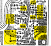
The dead capacitor is "CF11", it's inflated.
It is connected to pin JF07 which should, if we believe the diagram, be powered under -25V but I measure 25V.

I find -13V on all the pins of transistors QF03 to QF10.

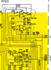
According to the P400 diagram (page 34) :
-25V should arrive to JF09 from transmitter (E) of transistor Q802 via J804 connector, white wire
I have -24 VDC on the white wire PF00 card side, whether the EQ Defeat is activated or not

-25V should arrive to JF07 from the emitter (E) of transistor Q801 via connector J805, white wire red line, I have 24 VDC on the white / red wire, is this normal?


so after I took the Q801, Q802, Q805 to Q808 transistor voltages measurements and I find abnormal things there too but I do not know how to interpret them.


How to understand the following measures?

first number : written in the diagram
second number : measured

Q801 :
E : -25V : 24V
B : 25,7 : 24V
C : 39,5 : 39V

Q802 :
E : -25 : -24
B : -40 : -39
C : -25,7 : -25

Q805 :
E : 6V : 6,2V
C : 26V : 25V
B : ? : 5V

Q806 :
E : 6V : -5,56V

C : 26V : -25V

B : ? : -6,26V

Q807 :
E : 36V : 25,81V
C : 26V : 25,53V
B : 35V : 39,3V

Q808 :
E : -36V : -25V
C : 26V : -39V
B : 35V : -38V


pin number : tension indicated in the diagram : tension measured


QF01 :
1 : 0 : - 13 VDC :
2 : - : -
3 : - : - 7 VDC
4 : -22 : - 17 VDC
5 : - : - 17 VDC
6 : 0 : - 13 VDC
7 : 0 : - 13 VDC
8 : 22 : - 13 VDC

QF02 :
1 : 0 : - 13 VDC :
2 : - : -
3 : - : - 7 VDC
4 : -22 : - 17 VDC
5 : 0 : - 17 VDC
6 : 0 : - 13 VDC
7 : 0 : - 13 VDC
8 : 22 : - 14 VDC

Thank you in advance for any help !

Have a good Sunday !

Eyton
 

Attachments

  • P400_PH00.PNG
    P400_PH00.PNG
    496 KB · Views: 12
  • page15.PNG
    page15.PNG
    442.5 KB · Views: 9
  • pf00_qf01_qf02_CF11.PNG
    pf00_qf01_qf02_CF11.PNG
    146.5 KB · Views: 16

bertus

Moderator
Hello,

You say that on the pins 8 of the QF01 and QF02 is -13 Volts.
The schematic states a value of +19 Volts.
The value of -25 Volts on the emittor of Q801 is stated wrong, it should be +25 Volts.

I see two 100 Ohms resistors between the +25 and +19, and -25 and -19 of QF01 and QF02.
Are these resistors OK.

PM500_resistors.png

The picture is a snapshot from a manual downloaded from eservice.

Bertus
 

bertus

Moderator
Hello,

Did you replace CF11?
If so, did you measure the voltage on it?
When the upper resistor ( RF09 in the schematic ) is broke, the voltage on it can be floating and causing the strange readings on the chips QF01 and QF02.

Bertus
 
Sir eytonbranhan . . . . .

If your power supplies outputs are ~ +25 and -25 at those stages that they feed, and are being there, all must be well and in accordance to this CORRECTED power supply print at the bottom.

My suspicion is . . . .

You have QF3-12 which are arranged in 5 sets of complementary /symmetry arrangements and should balance out in their voltage swings and current demands in their handling the 5 sections of frequency selective nodes of the equalizer.
If their is an imbalance (leaky or shorted transistor) that throws the common demand of all of them off, it will swing the power supply balance askew.

Now, it's blurry, but looks like ? RF13 ? . . . a 100 ohm resistor, couples in the +25 supply to its companion CF11 + filter .
Likewise an also even blu r r r r r ier ? ? ? RF09 ? ? ? is coupling in the -25 v supply to its CF12 - filter .
You can make a quick check of any power supply drain imbalance by measuring the voltage across each of those 100 ohm resistors .
An imbalance will be shown by one of the voltages being appreciably higher.
You could have a transistor, of those 10, that is shorted or one that has its emitter open . Creating a big time imbalance then.

Reference Schematic of + and - 25 Supply Source . . . . .

upload_2019-11-18_3-40-55.png


73's de Edd . . . . .

Why should I waste time learning from my past, when I am all too busy now, worrying about my future?
 
Last edited by a moderator:
Hello,

You say that on the pins 8 of the QF01 and QF02 is -13 Volts.
The schematic states a value of +19 Volts.
The value of -25 Volts on the emittor of Q801 is stated wrong, it should be +25 Volts.

I see two 100 Ohms resistors between the +25 and +19, and -25 and -19 of QF01 and QF02.
Are these resistors OK.

View attachment 46487

The picture is a snapshot from a manual downloaded from eservice.

Bertus
Hi Bertus,

sorry for my late reply.

thank you for confirming me that the -25V written on the diagram is wrong and we have to read 25V, that's what I suspected.

I checked the two 100 Ohms resistors, RF09 and RF10.

rf09_rf10.png

listing_PF00_resistors.PNG

I'm probably wrong but I think these resistors are 47 ohms ! ???
Is that right ? (Yellow, Violet, Black, Gold)

I unsoldered and measured them :
first one : 0,810 Kohms
second one : 0.L Mohms (seems to be definitively dead)

What's your opinion ?

Thank you again for the help !

Eyton
 

bertus

Moderator
Hello,

You are right, the resistors are indeed 47 Ohms.
Both readings are off.
0,810K is 810 Ohms
0,L is open leads.
I would replace bothe with the in the manual mentioned 100 Ohms resistors.

Bertus
 
Hello,

You are right, the resistors are indeed 47 Ohms.
Both readings are off.
0,810K is 810 Ohms
0,L is open leads.
I would replace bothe with the in the manual mentioned 100 Ohms resistors.

Bertus

Hello Bertus,

ok thank you I will change these two resistors by 100 Ohms resistors and let you know.

It will take one or two days… Thank you again !

Eyton
 
Hang on.
I wouldn't change any values. The parts listed in the manual doesn't match what you have. Notice RF01 and RF02 are 33kΩ and manual says 22kΩ? This thing was working for years the way it was and you shouldn't have to alter it.

Try reading resistance values again with your meter in the 1x scale. (If your fingers touch both test leads it can throw off an ohm reading in the KΩ range) You only need to unsolder one lead at a time for testing.
Which resistor reads open?

I would hold off ordering/replacement of parts until you have evaluated all the parts you may need.

Parts are cheap, shipping is expensive.
 
Thank you for your reply.

Mmm yes this is weird...you're right, I should change by same values...

I double-checked these resistors twice and without touching the leads.

But I already completely unsoldered both resistors from the board so I can't tell which one is open...

What should I do now ?
 
If you look at the node on the left (neg) side of your bad cap (cf11) you see it connects to pairs of 47k resistors feeding the base of transistors. I'd try pulling them out to try and isolate a short circuit. As Edd said, probably one of the transistors is shorted.
Once resistors are out, compare ohm readings to ground in each grouping. They should have similar readings.

If you find low resistance, you know there's a bad apple somewhere.
 
I also could check if a transistor is shorted by doing a continuity test between each of his pins ?
Is it a reliable test ? Or do you advise me to do as you said ?
 
Hello,

Did you replace CF11?
If so, did you measure the voltage on it?
When the upper resistor ( RF09 in the schematic ) is broke, the voltage on it can be floating and causing the strange readings on the chips QF01 and QF02.

Bertus

yes I replaced CF11 but it's dead again (it was before I pulled out the two 47 Ohms resistors)
I did not measure the voltage on it : /
 
Sorry, I wouldn't power it up yet.

It's hard to follow blurry on my phone screen.

I think your voltage measurements are out of kilter in part because of the open resistor.

It's possible that cap could be failing because of wrong polarity, rather than overcurrent from a short. 47k would not alow enough current to flow for a short.
The resistor on the other hand must have had serious current flowing through it to blow it apart. I presume RF09 was the one open circuit.

Anyway, a more practical approach instead of chasing circuit measurements, might be to pull and check components that are suspect.

I would start by checking diodes and transistors for shorts.
Yes, you can do a continuity test between pins to look for a short but it only tells you the component is shorted. Not that it's good.
It's better to use the diode check feature of a Dvm. Try googling how to check transistor.

Keep track what component came out of where on the board.

The good news is that you have other similar components to compare with.
 
I changed RF09 and RF10 by new 47 Ohms resistors found in some boxes
I also changed CF11 again

Good news : now I can hear a good sound with the EQ activated !

There is still a problem: when RF21 (the fader at the very left of the EQ panel) is at the max top, the signal (sound) is at least 5 times stronger !... I wonder if it could not be the cause of burnt RF09, RF10 and CF11, what's your opinion ?
 
Hey, great progress!
I don't think R21 would cause those problems. More than likely a transistor.

Does the volume transition quiet to loud fairly evenly (linearly) and then jump up in volume only at the spot at the extreme top position? This could be a bad pot.
If accessible, I would just transplant it with a 50k pot next to it. If the problem follows, you know it needs replacement.

If the level is quieter than normal and then jumps up, it its likely something else.

Looks like RF21 feeds the base of QF03 to control that slider frequency. I would check it and the surrounding components. It also controls input to opamp QF01.
Ceramic caps usually don't go bad, but it wouldn't be a bad idea to just replace all electrolytic caps do to their age.

I would also verify that the voltage rails are now reading correctly. Check voltage with Rf21 at top position, and again sliding it down.
 
Sir eytonbranhan . . . . .


Your RF21 pot is being associated with your QF03 stage which is likewise related to the lowest frequency aspect of your audio spectrum control . . .which I woulld suspect to be marked as being 50 or 60 Cycles / Hertz.
SO . . . that pots adjustment, should be more noticable than either a mid range RF23 or treble end RF25 of the audio spectrum, pots end to end adjustment.

Your two 47 ohm resistors being involved were related to being series isolating resistors for their associated CF11 and CF 12 positive and negative power inputs to the PF00 board for filtering and decoupling functions..
They were even being more robust METAL FILM resistors, rather than all of the the nearby CARBON FILM resistors.
See their assigned triangular / exclamation mark . . . .special part / exact type replacement . . . designation.

Was your failure fault of the CF11 being a short or leaky condition, as an opening of one of those resistors could result in a potential opposite polarity voltage being across one of the opposite side filters.

If you look at your post #5 photo at the dead center of the RF9 and 10 resistors, they show a discoloring, transitioning from grey/towards/ white discoloration, from referencing to the original case coloring at the ends.
Those have been heat stressed /overloaded. The RF09 seeming a bit moreso.
I would guess that your . . ." found" . . . . . presetly installed resistors, would be CARBON FILM or old composition types . . . . does a finger temp test applied to them, reveal any excess warmth ?

You might further do a DC voltage reading across each of them and use the received voltage and resistance values to then use OHMS law to compute the wattage that each is now presently handling.
There is usually a 400% overloading to have blown open the ORIGINAL METAL FILM resistor..

I REALLY was expecting your problem to be failure / breakdown within QF01-QF-02 pre amp I.C. 's ,of their pins 4 and 8, as they DIRECTLY connect to those RF9 and 10 resistors .

If you analyze all of the QF03-QF12 transistors, circuitrys, related resistors, none of them are being of such a LOW enough resistance to permit the level of power that would have been neccessary to blown RF9 and 10 resistors.

Also place volume all the way down and test DC voltage across all of the 100 ohm collector resistors of QF03-QF13 transistors, logging each down, then comparing for sameness / balance.

Also do the same test across the 4.7K emitter resistors of those transistors.
(Now you can see how even a dead shorted transistor(s) and those series 100ohm + 4.7K resistors could not even slightly start to create the overload situation to blow one of those RF9 and 10 resistors.)

Thaaaaaaaaaassssssit . . . . .

73's de Edd . . . . .


Illiterate?… write for FREE HELP!
shy-fart.gif


.
 
Hey, great progress!
I don't think R21 would cause those problems. More than likely a transistor.

Does the volume transition quiet to loud fairly evenly (linearly) and then jump up in volume only at the spot at the extreme top position? This could be a bad pot.
If accessible, I would just transplant it with a 50k pot next to it. If the problem follows, you know it needs replacement.

If the level is quieter than normal and then jumps up, it its likely something else.

Looks like RF21 feeds the base of QF03 to control that slider frequency. I would check it and the surrounding components. It also controls input to opamp QF01.
Ceramic caps usually don't go bad, but it wouldn't be a bad idea to just replace all electrolytic caps do to their age.

I would also verify that the voltage rails are now reading correctly. Check voltage with Rf21 at top position, and again sliding it down.

hello ! and thank you again for your help !

the volume transition is pretty violent but not at the extreme top position, it begins a little bit before it, like 3 or 4 mm before, maybe more.

It seems that only the left speaker is impacted by this thing, but it's not sure.
I checked this on the both speaker systems, 1 and 2 and the result is the same.

I also inverted QF03 with QF04 and CF31 with CF32 but again the problem is when RF21-1 is high enough.

for the rest of your proposals, I will try all that and come back.
 
Sir eytonbranhan . . . . .


Your RF21 pot is being associated with your QF03 stage which is likewise related to the lowest frequency aspect of your audio spectrum control . . .which I woulld suspect to be marked as being 50 or 60 Cycles / Hertz.
SO . . . that pots adjustment, should be more noticable than either a mid range RF23 or treble end RF25 of the audio spectrum, pots end to end adjustment.

Your two 47 ohm resistors being involved were related to being series isolating resistors for their associated CF11 and CF 12 positive and negative power inputs to the PF00 board for filtering and decoupling functions..
They were even being more robust METAL FILM resistors, rather than all of the the nearby CARBON FILM resistors.
See their assigned triangular / exclamation mark . . . .special part / exact type replacement . . . designation.

Was your failure fault of the CF11 being a short or leaky condition, as an opening of one of those resistors could result in a potential opposite polarity voltage being across one of the opposite side filters.

If you look at your post #5 photo at the dead center of the RF9 and 10 resistors, they show a discoloring, transitioning from grey/towards/ white discoloration, from referencing to the original case coloring at the ends.
Those have been heat stressed /overloaded. The RF09 seeming a bit moreso.
I would guess that your . . ." found" . . . . . presetly installed resistors, would be CARBON FILM or old composition types . . . . does a finger temp test applied to them, reveal any excess warmth ?

You might further do a DC voltage reading across each of them and use the received voltage and resistance values to then use OHMS law to compute the wattage that each is now presently handling.
There is usually a 400% overloading to have blown open the ORIGINAL METAL FILM resistor..

I REALLY was expecting your problem to be failure / breakdown within QF01-QF-02 pre amp I.C. 's ,of their pins 4 and 8, as they DIRECTLY connect to those RF9 and 10 resistors .

If you analyze all of the QF03-QF12 transistors, circuitrys, related resistors, none of them are being of such a LOW enough resistance to permit the level of power that would have been neccessary to blown RF9 and 10 resistors.

Also place volume all the way down and test DC voltage across all of the 100 ohm collector resistors of QF03-QF13 transistors, logging each down, then comparing for sameness / balance.

Also do the same test across the 4.7K emitter resistors of those transistors.
(Now you can see how even a dead shorted transistor(s) and those series 100ohm + 4.7K resistors could not even slightly start to create the overload situation to blow one of those RF9 and 10 resistors.)

Thaaaaaaaaaassssssit . . . . .

73's de Edd . . . . .


Illiterate?… write for FREE HELP!
shy-fart.gif


.

Hi Edd, thank you for the help, your explainations are very interesting !
(but I'm not sure to understand all of them lol...)

for the centers of RF09 and 10, yes you're right, the picture I took is a bit blurry but when I look at the old resistors, there is definitevely something weird at the center of each resistors.

Yes you're right again, I put two 47 ohms "basics" resistors instead of metal film resistors but a finger temp test doesn't reveal a lot of heat. It's just a bit "lukewarm".

For the rest, I will do all what you suggest and come back !
 

bertus

Moderator
Hello,

When you say that there is a sharp transition 3-4 mm before the end, it sounds like a bad potentiometer.(the shift regulator).

Bertus
 
Hello Bertus !

thank you for your reply !
ok, yes it seems consistent !

By the way, I checked with the left speaker disconnected (I should have done that earlier...) and there is no problem of fried sound like that... (if it can help to identified the cause...)

Eyton
 
Top