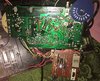
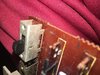
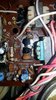
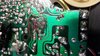
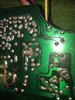
Very unfortunately, I left the batteries in my radio and it's now in need of repair. A smaller circuit board had just a dusting of corrosion. After thoroughly cleaning the small board all channels now come in, but volume is only audible and sound is somewhat distorted (not scratchy, just not quite right). So I peaked under the large circuit board and found significant green corrosion in one smallish area. Some of the traces/pads is this area seam to be missing, however all components test good.
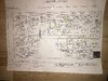
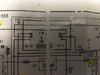
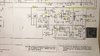
I found the schematic of the radio but don't know how to properly read it. I can use hook-up wire but not sure where to place it.
Here are some current questions hoping for help with:
1. Should the emitters of Q9 & Q10 be connected? (currently there is no continuity)
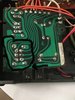
2. Looks like R41's lead towards the middle of bad area should connect to Q9/Q10 emitters? Currently, that resistor pad is lifted and rocks in place with no continuity to emitters?
3. Other connection concerns in circled area include all 7 components in suspect area. ((2 transistors, 2 resistors, 2 ceramic caps, and the three legs on one side of a connecting transformer). Specifically, what continuity tests should I do - between all these pads?
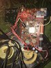
4. Both the radio's speaker and headphone were working at a low volume, but did not sound the best. Cleaning the green corrosion, and my attempted feeble repair may have changed something so I am reluctant to test radio's sound again for fear of blowing a component(s). The battery compartment is not currently useable so all prior tests were on the AC switch.
I already tried bridging one emitter to suspect resistor but that fell off when I also tried to bridge the two emitters -- so I just removed them both, and back to square one. Plan 2 was to lasso the 2 emitter pins to the lifted resistor pin. But, truthfully I'm an electronics knob, and rather than chasing uneducated hunches, I was really hoping for assistance with a better thought-out overall plan for returning this corroded area back to working correctly again, and hopefully having a nice radio one again.
Thank you in advance!
I found the schematic of the radio but don't know how to properly read it. I can use hook-up wire but not sure where to place it.
Here are some current questions hoping for help with:
1. Should the emitters of Q9 & Q10 be connected? (currently there is no continuity)
2. Looks like R41's lead towards the middle of bad area should connect to Q9/Q10 emitters? Currently, that resistor pad is lifted and rocks in place with no continuity to emitters?
3. Other connection concerns in circled area include all 7 components in suspect area. ((2 transistors, 2 resistors, 2 ceramic caps, and the three legs on one side of a connecting transformer). Specifically, what continuity tests should I do - between all these pads?
4. Both the radio's speaker and headphone were working at a low volume, but did not sound the best. Cleaning the green corrosion, and my attempted feeble repair may have changed something so I am reluctant to test radio's sound again for fear of blowing a component(s). The battery compartment is not currently useable so all prior tests were on the AC switch.
I already tried bridging one emitter to suspect resistor but that fell off when I also tried to bridge the two emitters -- so I just removed them both, and back to square one. Plan 2 was to lasso the 2 emitter pins to the lifted resistor pin. But, truthfully I'm an electronics knob, and rather than chasing uneducated hunches, I was really hoping for assistance with a better thought-out overall plan for returning this corroded area back to working correctly again, and hopefully having a nice radio one again.
Thank you in advance!
Attachments
Last edited:
")