Maker Pro
Maker Pro

Two relays in series with flyback diode.

My question has to do wth the flyback diode in the below described circuit.
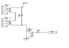
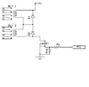
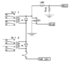
I have two relays in serries (6V coil each) that are connected to a 12V source and controlled via a logic gate mosfet. I know that a flyback diode has to be placed as close th the relay's coil as close as possible but the relays are about 3 inches appart from each other on the PCB.
What would be the best place to put the flyback diode to protect the mosfet ?
How would you connect the flyback diode if you had to in the circuit shown below ?
the circuit diagram is attached below.

Thank you so much.
 

Attachments

  • RELAYS.png
    RELAYS.png
    4.6 KB · Views: 27
Thats right davenn. I need to switch 4 sets of poles (4PDT) but it is critical for my circuit that theese contacts are at the same state even under fault conditions. So running them in serries, i make sure that if one of the relay ciols fail of if the driving transistor fails then all contacts will either be at NO state or NC state. Does that make sense ?
I could always try to find a 4pdt relay but then it would cost alot more and i would have to re desing my pcb's. it's easyer running them in serries.

As you do not show your application, it is impossible to argue for or against as you come up with these particulars, not in your original posting but well after someone makes a statement.
Difficult to keep up with such things I'm sure you would agree.
The "fail safe " arrangement may not work the way you expect in the event that one relay winding suffers shorted turns for any reason.
 
Last edited:
One other thing that comes in mind is adding a serries fuse. The relay coils according to the datasheet are 90 Ohms each. (SCHRACK RT424006). the current they consume under normal circumstances are about 66mA. Considering Ohms law, two relays in serries under 12V should still consume 66mA. If something happes to one relay then a fuse of say 80mA should be more than enough to cut open the circuit.
I have been trying for days to find a suitable fuse for that and came up empty. The fuses i found are rated 250V or so thus under 12V they can withstand alot more current before they go open. Arent there low voltage DC fuses rated at 80ma ?
 
The fuses i found are rated 250V or so thus under 12V they can withstand alot more current before they go open.
Incorrect. The voltage and current ratings of a fuse are independent. The 250 V rating means that it can interrupt a 250 V circuit without internal arcing or bursting the case. A 0.063 A / 250 V fuse will work just fine at 5 V, 12 V, whatever.

63 mA, 80 mA, and 100 mA are common values; also available in SMT.
https://www.digikey.com/products/en/circuit-protection/fuses/139?k=fuse&k=&pkeyword=fuse&sv=0&pv343=374704&pv343=403741&sf=0&FV=-1|18,7|3,7|8,49|1,49|326748,1989|0,mu100mA|2088,mu125mA|2088,mu60mA|2088,mu62.5mA|2088,mu62mA|2088,mu63mA|2088,mu75mA|2088,mu80mA|2088,-8|139,16|248782&quantity=&ColumnSort=0&page=1&stock=1&pageSize=25

ak
 
I am pretty sure i have read somewhere on the internet on a specific datasheet that a fuse (not a PTC one) with different voltage rating had different tolerance concerning its current rating.
To be honest i have witnessed countless times the fast blow glass fuse on my bench psu withstanding 3-4 Amps more than its current rating for a few seconds.
 

Harald Kapp

Moderator
Moderator
If something happes to one relay then a fuse of say 80mA should be more than enough to cut open the circuit.
If a relay fails open circui, current is interrupted and a fuse is not required.
If a relay fails short circuit, you can still turn off current using Q1. You can monitor the relay current either by using a small sense resistor in Q1's source path or using the Rdson of Q1. In case of a short circuit pf one relay coil current will nearly double and Vds will also double. You can use this as an indication of overcurrent and turn off the gate drive to Q1.

Question: how are you going to protect the circuit from a short circuit between drain and source of Q1? A fuse is useless as it can not distinguish between a broken mosfet or a controlled turn-on of the mosfet. You'd have to have two transistors in series for this purpose. A typical arrangement uses complementary mosfets:
upload_2020-1-6_12-40-48.png

The complementary mosfets require complementary drive signals (and a level shifter for the high side mosfet). Creating these complementary signals by two different I/O-pins of the controller (assuming you use a controller here) maximises the resistance to a single fault in one of the control lines as you always have to control both signals to turn the relays on.
 
I am pretty sure i have read somewhere on the internet on a specific datasheet that a fuse (not a PTC one) with different voltage rating had different tolerance concerning its current rating.
I'm sure that if you compare an automotive (32 V) fuse with a generic 1/4" (250 V) fuse, the timing characteristics could be quite different. But most of that is because automotive fuses are designed for a specific application environment.
To be honest i have witnessed countless times the fast blow glass fuse on my bench psu withstanding 3-4 Amps more than its current rating for a few seconds.
You have to be careful when comparing different fuses. Fuses are highly non-linear devices, and the data sheet charts are critical when trying to predict performance.

Without getting into specialty products, "normal" fuses come with different timing characteristics. The two most common are fast blow and slow blow, or "slo-blo". Also, all fuses are slightly overrated to account for manufacturing tolerances and prevent accidental blowing when there is no problem. Industry wide, it is considered better for a 1 A fuse to pass 1.5 A then to blow at 0.95 A.

The governing parameter is called "I-squared-t", the product of the current squared times time. As current increases above the trip point, the time the fuse can hold on before blowing decreases geometrically. It is not a perfect relationship, but it is a good way to compare the relative merits of different products.

Here are two datasheets. Note that the hold or delay times for a 1 A fuse at 2 A. In one case it is 0.52 s and the other is 4 s, a difference of over 8x.

ak
 

Attachments

  • Bus_Ele_DS_2002_MDA_MDA-V.pdf
    275.3 KB · Views: 1
  • Buss-ABC-2000.pdf
    81.2 KB · Views: 1
Last edited:
If a relay fails open circui, current is interrupted and a fuse is not required.
If a relay fails short circuit, you can still turn off current using Q1. You can monitor the relay current either by using a small sense resistor in Q1's source path or using the Rdson of Q1. In case of a short circuit pf one relay coil current will nearly double and Vds will also double. You can use this as an indication of overcurrent and turn off the gate drive to Q1.
Question: how are you going to protect the circuit from a short circuit between drain and source of Q1? A fuse is useless as it can not distinguish between a broken mosfet or a controlled turn-on of the mosfet. You'd have to have two transistors in series for this purpose. A typical arrangement uses complementary mosfets:
View attachment 46854
The complementary mosfets require complementary drive signals (and a level shifter for the high side mosfet). Creating these complementary signals by two different I/O-pins of the controller (assuming you use a controller here) maximises the resistance to a single fault in one of the control lines as you always have to control both signals to turn the relays on.

All The above are correct. I will use the fuse anyway just in case it will go open faster (though very unlike) than the relays coil thus saving the relay.
I do use an MCU to control the mosfet and i use a voltage sense resistor network. When the relays are disengaged i read the 12Volts stepped down to 4.5 on the mosfet's drain. When the relays are engaged i read 0V on the mosfet's drain.
I have no way of knowing that the mosfet is shorted unless i give a "disengage" command but i do not really care about this condition because a shorted mosfet will keep both relays engaged untill i need them disengaged in which case my MCU will detect that the relays faild to disengage. Do i make sense ?

You can monitor the relay current either by using a small sense resistor in Q1's source path or using the Rdson of Q1.

This sounds interesting could you please explain to me how because i do not know how to do it?
 

Attachments

  • image.png
    image.png
    13.7 KB · Views: 5
Top