2 channels can be used with the changeover or spdt relays as shown in the video you linked.
Previously I assumed you were using
spst relays.
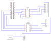
The H-bridge is constructed this way:

I can't draw the connections into your diagram as I have no idea what it shows.
"coil for relay 1" is a placeholder for the control of relay 1 via the input pins on the relay pcb. Same for relay 2.
This circuit definitely requires limit switches because without power to the relays the actuator will see the full supply voltage.
Here is an improved version of the circuit:

Note that the nc and no contacts of relay 2 are swapped here. The advantage of this circuit is that without power or control signals to the relays both sides of the actuator are at the same supply voltage (positive in this case) and therefore the effective voltage across the actuator is zero. The actuator will not move.
To move the actuator, you either activate relay 1 or relay 2, never both at the same time.
Assuming the circuit as shown above, activating relay 1 will apply neg. voltage to the left side of the actuator and pos. voltage to the right side.
Activating relay 2 instead (and de-activating relay 1) will apply pos. voltage to the left side of the actuator and neg. voltage to the right side.
Limit switches will prevent the motor within the actuator from overload when the actuator reaches either end of its travel distance.
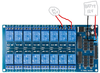
The idea to add the ULN2803 comes from a forum on raspberrypi.org
Basically correct, but as you can see on the photos of the pcb these drivers are already installed.