Maker Pro
Maker Pro

Relays

hevans1944

Hop - AC8NS
You refer to an h-bridge, do you?
That wasn't what I was thinking. I was thinking more along the lines of the picture below with the DPDT switch replaced with a DPDT relay (a relay with two Form-C contacts):
upload_2020-4-18_16-3-4.jpeg
But your link to the H-bridge arrangement works well with two Form-C relays, and it doesn't require another relay to turn the motor on and off:
H%2BBridge%2Brelay.png

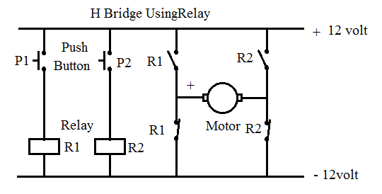
I think I like the H-bridge arrangement better, but a DPDT (two Form-C contacts) relay for direction control, along with a second relay (SPST or DPDT) to switch power on and off to the motor, allows for independent direction and motor on/off control, and is the way I have always implemented DC motor controls. I think the H-Bridge version is better because (1) the motor is de-energized if neither relay is actuated; (2) the motor runs in the appropriate direction when either relay is actuated; and (3) the motor windings are shorted and the motor does not run if either both relays are actuated simultaneously or both relays are de-actuated simultaneously. Therefore Relay 1 could be labeled FORWARD and Relay 2 could be labeled REVERSE.

More importantly for @Goldhelmeth's project, the H-bridge circuit only uses two of the four SPDT relays on his Bluetooth remote-controlled relay board. That leaves one relay available for controlling a fan and another relay to turn on a hot-plate to heat water for a French-press coffee maker... the finest way to make a cup of coffee IMHO. All this might be a moot point since the 4-channel Bluetooth module has now been replaced with a 16-channel module controlled by a Raspberry Pi microcontroller or minicomputer or whatever you want to call it. That's a pretty big step up for someone who yesterday didn't know diddly about electronics or electrical circuits!
 
I beleive I can... May I add another line on the stupid-questions list ? Lets say I wanted to power a fan 12v I would have to plug one end of the battery to normally closed, and the other end to the fan and the other end of the fan to common right ?
 
I beleive I can... May I add another line on the stupid-questions list ? Lets say I wanted to power a fan 12v I would have to plug one end of the battery to normally closed, and the other end to the fan and the other end of the fan to common right ?

If you want the motor to run when the relay coil is powered.
Positive of battery to common, normally open (n/o) contact to the motor.
Naturally battery negative directly to motor negative.
If motor spins wrong direction, reverse motor leads.
 

hevans1944

Hop - AC8NS
If I understand this correcly, the only difference between 5v relay board and 12v is the power supply of the board ? So can I use a 5v relay board to control a 12v motor ?
Yes.

Generally. A 5V relay board will have relays whose coils operate from 5V DC and a 12V relay board will have relays whose coils operate from 12 V DC. The switching contacts of the relay(s) on either board are isolated from other circuitry on the board, including the switching contacts on other relays, and have their own voltage and current ratings. Think of a relay as an electrically-controlled switch... which it is.

The electromagnetic coil of the relay performs mechanical and electrical isolation between the switching contacts of the relay and the rest of the world. This means the relay coil can have just about any voltage and current requirements imaginable. The same can also be said of the relay switching contacts, because the coil and the contacts are independent entities, electrically and physically isolated from each other.

A common coil voltage for relays is 120 V AC or 240 V AC for industrial applications. The switching contacts for those relays might be rated at 600 V AC and 200 A while another relay with the same coil voltage specifications might only be rated for 24 V DC and 2A. There are infinitely many combinations possible, but clearly only a finite (but large) number are actually manufactured.

You can power a motor, switching power to it through relay contacts on either a 5V relay board or a 12V relay board. If the motor voltage rating is the same as the relay board rating, both motor and relay board can be powered (in parallel) from the same power supply. If the motor voltage rating is higher or lower than the relay board voltage rating, then a separate power supply arrangement must be made to accommodate the difference in voltages.
 

Harald Kapp

Moderator
Moderator
I don't understand I thought you told me that the supply that powers the board cannot power the motor through the channel because it is only a switch
Right, but if you have a 12 V system, for example in a car, you can use the same 12 V power supply to power the board and the actuator. The connection to the actuator still goes through the contact side of the relays and has to be wired separately.
 

hevans1944

Hop - AC8NS
May I add another line on the stupid-questions list ?
There are no stupid questions, but I have seen a LOT of stupid answers in my life. So, ask away! Also, see @bertus second and third tag lines at the bottom of each of his posts with regard to his opinion (and mine) regarding so-called stupid questions.
 
Top