Maker Pro
Maker Pro

The Ultimate Tube RIAA-Amplifier?

You are too kind, Chris!

By the way, how is the weather down in Florida?

Here winter is sneaking up on us (just above 0C...=32F?)

But it has been a mild winter so far. I think I've never experinced a more mild winter.

Take care!

Best regards, Roger
 

CDRIVE

Hauling 10' pipe on a Trek Shift3
Roger, I'm not being kind at all. If I didn't like what I saw I would have either not commented or I would have made a sarcastic remark. Odds are it would have been the latter! :p YOU DO FINE WORK! ;)

The weather here in South Florida? I opened up the house two weeks ago but I told the wife that if it doesn't drop to below 70 tonight I'm closing it back up and firing up the AC. It's been beach weather!

Chris
 
Last edited:

(*steve*)

¡sǝpodᴉʇuɐ ǝɥʇ ɹɐǝɥd
Moderator
My wife told me the forecast was for 104F here today.

I'm looking forward to being able to go outside without freezing... :p
 
Hi dear folks!

Today I attached labels to all the connectors and switches.

It didn't turn out so good :D

They got askewed in spite of me trying desperatelly to keep them straight.

The fault got to be my stubborness use of Microsoft's simple and brilliant MS Paint.

There exists however no real problem because these crazy pre-amps will hardly be manufactured by the lots :D

Take care!

Best regards, Roger
PS
Steve, it sounds like you live in the desert :D Summertime here in Sweden, the temperature hardly goes above those 104F and now it's winter...

Chris, in spite of what you say I still think you are kind ;)
 

Attachments

  • DSCN0537.JPG
    DSCN0537.JPG
    50.4 KB · Views: 165
Now I have finally started to solder my pre-amps. I started with the heater windings which uses a ground-balancing potentiometer. This solution is of course not "ultimate" with regard to resulting hum levels but it is "ultimate" with regard to simplicity.

Moreover, the residual hum level might not even be possible to hear (unless you put your ears close to the loadspeaker or is using headphones). Anyway, it is exciting to test this primitive solution once and for all.

I have carefully selected the triode-section which seem to be least sensible to hum (high pin numbers).

I am attaching a photo of my slight progress.

Best regards, Roger
 

Attachments

  • DSCN0540.JPG
    DSCN0540.JPG
    57.2 KB · Views: 136
Hi!

I have now soldered all supplies which means heaters for both the cossor and the amplifying tube as well as its pre-filtered DC-supply.

Next step will be to RC-filter the supply for the anodes once more. When I have done that the residual 100Hz hum will be nonaudible, guaranteed.

The 50Hz-heater hum will however be audible. The only question is how audible it will be and if that level really is disturbing. Sorry for nagging about that :D

Attaching some photos of my slight progress.

Best regards, Roger
PS
Except for 50Hz hum, I think this amp will be very quiet. Even though I do not like that I'm really not using my preferred "Guarding-methode" consistently. There is thus a potential difference between the ground-return (guarding-point) and the signal ground-return due to the copper chassis.

But this difference will be the same (same ground connection) for both the incoming as well the outgoing signal and thus will not be audible (at least that is what I think :D)
 

Attachments

  • DSCN0541.JPG
    DSCN0541.JPG
    58.8 KB · Views: 189
  • DSCN0542.JPG
    DSCN0542.JPG
    41.6 KB · Views: 137
I have now soldered the last step of the mains supply filtering (one cap for each anode).

Tomorrow I will solder the BJT and the RIAA filter.

Doesn't sound that exciting but it is :)

Take care!

Best regards, Roger
 

Attachments

  • DSCN0543.JPG
    DSCN0543.JPG
    54.4 KB · Views: 119
  • DSCN0545.JPG
    DSCN0545.JPG
    44.4 KB · Views: 124
I have now soldered all filters except RIAA. All that is left i thus RIAA and cableing.

Merry Christmas!

Mest regards, Roger
 

Attachments

  • DSCN0546.JPG
    DSCN0546.JPG
    51.6 KB · Views: 148
  • DSCN0548.JPG
    DSCN0548.JPG
    50.3 KB · Views: 120
  • DSCN0549.JPG
    DSCN0549.JPG
    53 KB · Views: 133
I have now soldered the last components being the RIAA filter and thus the blue capacitors up to the left. The next and final step is cableing.

Best regards, Roger
 

Attachments

  • DSCN0552.JPG
    DSCN0552.JPG
    52.1 KB · Views: 137
I have now finished all the cableing. And changed a capacitor between the first tube's anode and the second tube's grid which happened to be 100nF/63V. I have now changed it to 100nF/250V. I have also changed the position of the RIAA-filter. It struck me that it was not so smart to have the "MIC-filter" on one side of the tube and the "RIAA-filter" on the other because this would complicate optimum screening.

The cables themselves are however not so trivial. They are pair-twinned with screen. For IN and OUT I have used one conductor (white) twinned with screen as ground and the other conductor (red) as signal carrier. This I think minimizes both electrical-field as well as magnetic-field interference. And is why I have bundled them all up even though the best way for a signal to interfere with another signal magnetically is if they are placed along eachother.

I did however think this was better than to rout the output over the high-current heater cables.

What do you think?

Best regards, Roger
 

Attachments

  • DSCN0555.JPG
    DSCN0555.JPG
    55.8 KB · Views: 155
  • DSCN0556.JPG
    DSCN0556.JPG
    57.4 KB · Views: 123
  • DSCN0553.JPG
    DSCN0553.JPG
    55.9 KB · Views: 110

(*steve*)

¡sǝpodᴉʇuɐ ǝɥʇ ɹɐǝɥd
Moderator
I can't tell you anything that would be useful :)

I've been watching it come along and it does look the part. You'll have to let us know how it performs.
 

CDRIVE

Hauling 10' pipe on a Trek Shift3
What can I say? It's pretty much what Steve said. Well, maybe one thing... I think RCA jacks are probably the worst connector ever developed. Regardless of the fact that they've been around since the 1940's, possibly even the 30's. I know that F connectors are well accepted as low cost but very effective RF terminations but they also beat the hell out of the old RCA jack and work equally well for audio as they do for UHF.. The plugs don't fall out of the jacks and make a solid connection! ;)

Chris
 
Thank you folks! :)

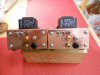
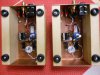
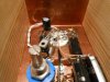
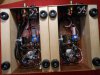
Today I applied some voltage to the units.

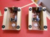
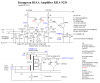
First I began by verifying all the connections. I began by verifying the transistors which were ok, next step was the 12AX7s and they were also ok. Then I got to the cossors. Jesus, I must have been drunk or something because nothing was right! I think I must have use those old and tiny databooks, looked at the EAA91 and looked away while it turned the page by itself. That's the only explanation I got :)

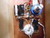
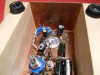
Anyway, I changed almost all the pinnings on EAA91 and continued verifying solderings and connections.

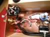
After I did this I plugged it in to my "Step Transformer" which I have built by my own while a Full Transformer is so expensive.

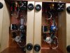
So I put it at 55V and verifyed some ac-voltages while there was no DC out after cossor, then I set it at 110V and suddenly I had 40V out. Good, I thought because heater effect is down -6dB yet some DC came out.

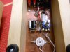
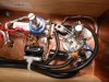
Next step was full voltage, 230V. Suddenly I got 12.5VAC@12AX7 and 4.6VAC@EAA91 and most joyful, 140VDC as raw supply!

I also did some bias probing and got plate voltages around 70V. Emitter output voltage at some 110V(@MM).

One last nice thing to mention is that hum level at the raw 140V was as low as 2mVe.

This while using a cossor, two 33uFs and one 15k resistor! But be aware that this rediculously low ripple is actually filtered once more :D

Tomorrow I will do the fun tests!

Best regards, Roger
PS
I will probably correct EAA91 heater voltage some. It needs more current and parallelling the 22R already sitting there is easy.
 

Attachments

  • KRA_8_Cossor_SE_ACH_2_Results.PNG
    KRA_8_Cossor_SE_ACH_2_Results.PNG
    43 KB · Views: 161
  • KRA_box_borr11_Cossor_5.PNG
    KRA_box_borr11_Cossor_5.PNG
    35.8 KB · Views: 129
Don't feel stupid, Chris!

I like using the European name for a rectifying tube. It is a more simple word. So a cossor is simply a rectifying tube.

I do however prefere "tube" over "valve" even though "valve" kind of tells more what it's all about.

Best regards, Roger
 
Last edited:

CDRIVE

Hauling 10' pipe on a Trek Shift3
Don't feel stupid, Chris!

I like using the European name for a rectifying tube. It is a more simple word. So a cossor is simply a rectifying tube.

I do however prefere "tube" over "valve" even though "valve" kind of tells more what it's all about.

Best regards, Roger

Thanks Roger, I was clueless. What does cossor literally translate to in Dutch? Is the term exclusive to a rectifier tube or more broadly used?

Chris
 
I have no clue whatsoever :)

The first time I saw the expression was in Wireless World (The Williamson Amp).

From then on I have thought that a rectifying tube is called a "cossor".

Best regards, Roger
 
A. C. Cossor Ltd. was a British Company producing tubes. Related to tubes, it is just a brand name, and not a tube type.

Wikipadia: http://en.wikipedia.org/wiki/A.C._Cossor

Hi gorgon!

I think you are wrong.

Attached is the original Williamson schematic printed in Wireless World 1947 (revised in 1949).

It clearly shows that the two rectifying tube types are called cossors and I even think that cossor means Full-Wave Rectifiers (like 5V4 and 53KU) only.

But I might be wrong :)

Best regards, Roger
 

Attachments

  • willcircuit.jpg
    willcircuit.jpg
    148.9 KB · Views: 173
Top