I must admit that all this information has me reeling.
Regarding space charge bias, I can't sim it, or to be more precise my sims on a 12AX7 don't validate it. I swept the grid resistor from 0 to 100Meg but the plate current didn't so much as twitch.
Regarding tubes that operated down to 12V B+ This is even more of a mind blower. I mean this stuff isn't just electronics history for me, I lived the era. My first car was a 1953 Plymouth. I know of no American autos that of that era that didn't have vibrator power supplies in them to generate the HV plate supply. Vibrators were the electromechanical predecessor to the solid state multivibrator. They looked like a chassis mount electrolytic.
I also owned vacuum tube portable radios. They employed an A battery for the fils and a 90V B battery for the plates. Military walkies of the early 60's had A & B bats too. This was all common stuff of the day. Heck, the best RF front end tube ever made was the 6CW4 (Nuvistor). It looked more like a transistor than a tube and was extremely small, Even at this mini size it didn't operate at the low voltages mentioned here. I can only assume that the ultra low voltage tubes were not very popular.
In the mid sixties I serviced hundreds of ARC34 UHF military aircraft transmitters. They also employed small pencil tubes in the multiplier and driver stages. The 90W output was delivered by Lighthouse tubes. The HV B+ was generated by a Dynamotor but later replaced with solid state multivibrator using Germanium power transistors. Not a great improvement. They'd make smoke if you looked at them wrong.
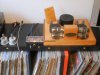
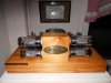
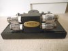
I'm a pack rat that finds it difficult to let loose of old stuff. Consequently I have kept just about every piece of test equipment and ham gear purchased or home brewed since 1966.
Off the top of my head I figure I have at minimum 25 items with tubes. One is a 1934 AM signal gen manufactured by General Radio for the Navy. Most of this stuff I haven't seen in years because they're buried deep in a storage bay.
Chris
Hi Chris!
I wrote you a long answer but it got lost due to some stupid feature that logs out people within less than half an hour.
I am tired now so it's just too much work to try to tell my story again.
But in short,
I like your story and I like your tube servicing experience as well as your collection of tube apparatus. Awesome!
I have done some calculations with the help of Duke37's papers and have come to the conclusion that low voltage tubes actually are possible.
Remember that J=2,34*10^(-6)*V^(1,5)/d^2 [A/m2] as stated in those papers.
This means that if d=1mm, A=1X2cm then I=0,5mA/V^1,5 or approximatelly 8mA@6,3V.
So it is possible with low voltage tubes.
The strange thing is however that I've never heard of them.
As you have pointed out, people used mechanical vibrators to step up the voltage in the past.
But ok, the ECC86 amplification factor is quite low (14).
You can download the pdf here:
http://www.r-type.org/search.php?zoom_sort=0&zoom_query=ECC86&zoom_per_page=10&zoom_and=1
I tried to attach it but it was too large (>97kB).
Take care!
Best regards, Roger
")