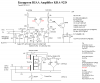
The ECC83 valve is equivalent to 12AX7 tube and also B139.
To be the ultimate, I would take the transformer off the chassis or at least use a conducting belt around it.
Hi Duke37 & Chris!
The first time I built these kind of amplifiers I used a CW-multiplier and stepped up 12Ve some 10 times.
This worked great but meant an irritating separate PSU.
My thought now is to use a standard 15V+15V transformer driven by 12V as noted.
The magnetic leakage from this transformer will probably disturb the signal somewhat.
But I am planning to use "remote" twinned and shielded wires for the signal.
And by using this transformer, all that is needed is that extra commersially available AC-adaptor (12V).
I have zoomed in on the problems always appearant while using common supplies so I have decided to build mono-blocks (no current-loops possible).
If 1N4007s are permitted, then why not use a full diode bridge, getting rid of the 6X4.
Some hum could be eliminated by using a 12.6V (or 6.3V) DC stabilised supply for the heaters.
The reasons are simple. One, a cossor will enable a smooth start (not that important here though because I will leave it on always, i.e no switch) two, the amplifier will simply look more nice than a single tube would
")
Regarding the heaters, you are right. But I like simplicity and those extra four components you need to use a regulator just messes things up while building "in-air".
And I can take some hum. Because let's face it, the vinyl records aren't that silent anyway
The high value (10M) grid resistors use grid current to bias the valve to -1V. I wonder how this voltage was measured and whether you can find a simulation model.
I have actually measured the grid bias using 10M (and those ~70Va which
might be important). They seem to stabilize at some -1V.
I think the largest gain using Edison-bias comes from the fact that any flaw a cathode capacitor might have will otherwise be amplified u+1 times.
There might also be a benifit regarding noise (because at least one channel is extremely silent).
I thank you both for your comments. It made me very happy!
Best regards, Roger
PS
Chris was confused about my BJT.
Well my reasoning is this.
An emitter-follower has an output impedance close to 1/gm (normally better than 100 Ohm for small signal transistors).
While loading the amplifier with no more than some 10k (common line-inputs are 47k), the variations in gm will not affect the signal whatsoever. The BJT will simply transform the high anode impedance (some 50k in my case) to some 100 Ohms and this while only affecting and disturbing only a fraction of the 100 Ohm-part.
The reason for not using some high-transconductance ECC81/12AT7 is simply because it isn't needed (and it complicates the design). A BJT will simply just do (note, ECC81 isn't that linear either but with the above reasoning...)