Maker Pro
Maker Pro

Stage Line 500W amp repair project

Yes all the outputs are new and never been installed, i realise this is a long post, in short it blew up and i was repairing it qith the help of the guys on here, due to sercumstanses it qas chucked on the back burner for about 3 years, now i have changed a shed load of parts and took many readings, i am back to where i started lol
 
So, quick probe around today, would appear D9 zenner 1N4004 is shot so giving me a dead short causing the fuse to blow, gonna have to order some spares
 
If you have put the + and - wires on the wrong way round, the likelihood is that you have blown the nuts out of all the semiconductors.

Before you started all of the dismantling, you should have carried out some basic tests such as check the power supplies to see if one or other is very low and or check the output voltage of the amplifiers. The initial problem could have been caused by a large O/P offset in one of the amps and the amplifier was not enabling the output in order to protect the speakers.
 
It's probably a bit late now but, it might be of some use to check the power supplies with the amplifier fuses out to see if they are OK. Is one of the amplfier's functioning correctly? If so some useful measurements may be made.
Have now had a quick squint at the schematics and it looks a bit of a nightmare in there. I think you need to completely isolate the power amps from everything including the PSU's. I note from the schema's that each amp has two sets of supplies ie ±45V for the power stage and ±55 for the front end. You need to establish that they are as they should be.
Ok, how do i do this ?
 
You just need to remove any fuses between the amps and the supplies and then measure them with a DMM to see if they are in range. ± a volt or two is OK. Any substantial deviation might indicate a PSU issue but I think that is unlikely.
 
It's probably a bit late now but, it might be of some use to check the power supplies with the amplifier fuses out to see if they are OK. Is one of the amplfier's functioning correctly? If so some useful measurements may be made.
Have now had a quick squint at the schematics and it looks a bit of a nightmare in there. I think you need to completely isolate the power amps from everything including the PSU's. I note from the schema's that each amp has two sets of supplies ie ±45V for the power stage and ±55 for the front end. You need to establish that they are as they should be.
Mesuring from the OVPL T20, negative probe, i get 64vDC at each fuse 2- 2+, fuse locations F1, F2, F3, and F4
 
So, i thought D9 was dead as it read the same either way round on the diode check setting, pulled it out and it reads fine, (replaced anyway), next tested Q1 from emitter to collector, it reads the same with the probes either way round,
The corresponding transistor on the right channel seems to read fine so think Q1 is dead, going to have to remove it and test out of circuit
 
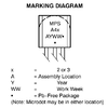
Removed and it reads dead short emitter to bass and bass to emitter, also reads the same emitter to collector and collector to emitter, so guess its shot , now the original one is mpsA42 E02, i cant seem to find replacements with the E02 part, is this important?
 
Last edited:

bertus

Moderator
Hello,

The MPSA42 is the part number, the E112 is likely a production code.
MPSA42_code.png

Bertus
 

Attachments

  • MPSA42-D.PDF
    101.9 KB · Views: 2
Top