Suggestion....
I know this is probably your first project, but a bit of advice...
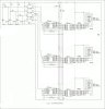
Always...always...always keep your schematic accurate. Always make your physical circuit match your schematic. If you do make changes to the physical circuit...always take the time to reflect the changes in your schematic. It will help you and others troubleshoot....
So...
One thing I noticed is the LED display part number. If I'm reading the datasheet right, the forward voltage drop of each segment is at least 7- 8 volts, and for 30ma its about 8.05 volts. That means your not going to be able to use a 5 volt power source. A 12 volt power source woud be better.
link to datasheet:
http://www.kingbrightusa.com/images/catalog/SPEC/sa40-19ewa.pdf
I'm still looking over the rest of the schematic...