12V is still within the operating conditions for the voltage regulator that feeds the left side of the circuit.Also: do you (can you) recommend a certain kind of IC socket for the 4033s and ULN2003s or are they all relatively universal?
regarding above..... When looking thru the parts I realized that I might have to decrease the resistors right before the 7 segment displays for a 12v power supply (to maintain correct power to LEDs). Does that make since? and will all the others suffer as well?
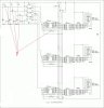
The led's get fed directly from the power supply though, so if you are decreasing the voltage, simply decrease the resistors to keep the current through them high. Using it as is will still produce results, but the leds will be dimmer.
As far as sockets are concerned, they are pretty universal. Components have gone through a sort of standardization so that you can buy a specific "package" for an IC and not have to worry about fiddling with pin spacing and the like. So, when it comes time to build this, I would suggest getting through-hole components. Get them in 'DIP' packages and you can build it on a prototyping breadboard to start. Once you ensure everything works as desired you move the parts from the broadboard and solder them to a 'perfboard' or 'stripboard' for a final product.
") these look like the right deal?
these look like the right deal?