Maker Pro
Maker Pro

Repair to Control Board PCB of Whirlpool Oven

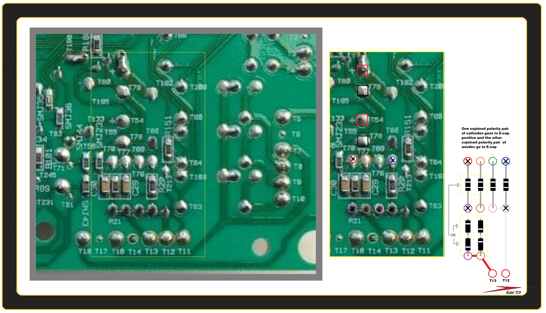
This Whirlpool Oven model RBD305PDB12 come on and goes off sometimes in months. So might work for several weeks then go off for months and then come back all of a sudden and work for a while again. I finally took out its Control Board and there is a carbon trace on it and where a diode mounts has damage. Please see the picture. I don't see any other damage on this board, pictures included. How can I repair this board? The board seems to have a little hole and I am not sure resoldering will be enough. I recently saw someone using super glue and baking soda as a repair for plastics. Would that work plus a resolder? Any help would be appreciated. Thank you.
https://drive.google.com/file/d/19GvLnyClx84ujM-7cRxCWANuRyn9FS-p/view?usp=sharing
https://drive.google.com/file/d/1Ywx5EK0WTTxYUL88ZLCvxEmwHQIa7PU3/view?usp=sharing
https://drive.google.com/file/d/1wdMgwNZxcWQZyEVgxO-1TsES3hmcHQT6/view?usp=sharing
https://drive.google.com/file/d/1Ox9ZA7RyF97rTQBy10Styc8CjNVgCTbE/view?usp=sharing
 

Harald Kapp

Moderator
Moderator
That could have been a resistor or a capacitor. As there is no clearly visible labeling I couldn't say for sure which of these. If you can decipher the letters here we may be able to at least know the type of component:
upload_2021-2-5_8-22-15.png

Without a schematic or a good board for reference one cannot determine which value the component should have. If you had access to a reference board, one could look at the component on that board or measure it.
As for the cause: it is burnt from overload. Why is a mystery. As this component is next to the diodes on the other side which seem to form a bridge rectifier) a voltage surge may be a possible cause - wherever that came from.
 
To answer your question about the markings on the board, I found a similar board picture on the internet and comparing that picture with the picture I took from the board, shows the marking at the burnt out sight to be C29 which I assume means Capacitor 29 (Please see the picture in the link below):
https://drive.google.com/file/d/1pqPHS9IiFLdxxlQQ1EC7C6CX6p_Ue8Yz/view?usp=sharing

How do I go about repairing this board?

If I recall correctly from reading an article a while ago, higher capacitance is always OK. Is this right? What is this type of capacitor called, someone with experience should be able to identify the type of the capacitor, assuming the other one next to the burnt out one and still intact is of a similar type.

The burnt out PCB area: what was there in terms of connection to the rest of the board? How can this area be repaired?

I found this wiring schematic in the oven:
https://drive.google.com/file/d/1TXvpDPAexB6aVtJjkk0HIGUEiSglAjFt/view?usp=sharing
I thought it might be helpful, at least to know how the oven works so I am including it here.

Thank you for your help.
 

Harald Kapp

Moderator
Moderator
I'm sorry.
C29 is the reference designator. With a schematic or a bill of material on the hand one could identify the required value. But not without.
If I recall correctly from reading an article a while ago, higher capacitance is always OK. Is this right?
No. This is o.k. for filter capacitors in a power supply, for example. But if the capacitor determines the frequency of a filter or an oscillator, this idea is plainly wrong. We don't know what it is doing here.
someone with experience should be able to identify the type of the capacitor,
It certainly is a ceramic capacitor, but type alone doesn't help. One would need a value. You could remove C30 (next to C29), measure the value and try the same value for C29. Probably chances aren't bad that it could work. Although this is by no means a scientific or at least an engineering type of answer ;). Of curse, put C30 back, too.
After removing the burnt C29, carefully clean the PCB and check the copper traces if they are still in good condition.

The wiring diagram doesn't show the components on the PCB so it is useless.
 
I cleaned the area a bit with acetone. I see there were 2 traces on pcb that seem to connected to the 2 terminals of the burnt out capacitor (please see the picture below).
https://drive.google.com/file/d/1Ogn9nhXKiJ8OvVSqYPOIcbIxM8c4mEwT/view?usp=sharing
https://drive.google.com/file/d/1ORSLwxrsX2aUAtAlkSdZT3Cms-rxvynY/view?usp=sharing

By the way after cleaning the area I see that the diode on the other side of the pcb has no connection to this capacitor the way I described on the first post of this thread. This capacitor is a separate component on the other side of the pcb.

Question: How can I tell which side of the capacitor goes to which terminal? Capacitors are marked with negative and positive.


Question: Can these traces be recreated with a strand of copper wire or copper tape adhesive? Or perhaps they are good enough that with a little extra trace created by solder they can be used as they are?

Question: What does the capacitor solder to, the terminals or to the board or both? This question might be very elementary but I am not sure how a pcb components attaches to the board when it doesn't have leads that go through the board, so please forgive my ignorance.

As for knowing the value of the capacitor by removing the adjacent one: I have always had problem desoldering components off a pcb so do not want to take the adjacent one off to measure it. Can you think of any other way that a solution can be found for this repair.

I am sending this reply right now without researching the problem further myself. I will however research more but I hope more useful information can be gained from your reply while I research it further too.

Thank you.
 
If anyone is familiar with these oven's operation: Can this burnt out capacitor cause the intermittent issue I described about the operation of this oven in the original post of this thread?
I remember I had a computer that had intermittent issues which were remedied (for a while before it broke completely) after some swollen capacitors were replaced. So perhaps these types of intermittent issues are often caused by faulty or in this case missing capacitors.

Thank you.
 
I am researching how to go about installing a new ceramic capacitor on this pcb. There should have been two little pads where the capacitor should be but they are burnt out. Can anyone suggest how to recreate these pads for the new capacitor? Or link me to some website or video that shows this? I am searching for these information myself but any help would be appreciated.
Thank you.
 
I found this very helpful video on how to repair components on a pcb that have damaged pads:

I checked and there is continuity between the ends of each resistor and capacitor pair as shown in the following picture:
https://drive.google.com/file/d/1YR64o3Ic7JeiPjxlHRbWDFOTvz0BbBFN/view?usp=sharing

Therefore I can run a wire from each end of the resistor next to the missing capacitor and that should restore this part of the pcb.

I am not sure how to fill the crater on the board. I thought of filling it with JB Weld glue, or put some baking soda and drip some super glue on it but I am not sure of either of these methods. JB Weld glue is strong but it maybe difficult to smooth it out without making a mess. The super glue/baking soda I am not sure what kind of repair that would make. Does anyone has a good suggestion for this?
In one of the videos I watched the person was using something called UV Solder mask which might work well but I rather find a solution that I already have like the 2 mentioned above.

After watching these videos I am more confident about removing the other capacitor to check its value but now I found out that my multimeter capacitance does not seem to be working. So need to find a solution for that. Any help in this regard would be very helpful too, is there no way to know a capacitance by the color of the component like with it can be done for resistors? S

till need to figure out which side of the capacitor goes to which side of the resistor, or does that matter?

I appreciate any help and guidance.

Thank you.
 

Harald Kapp

Moderator
Moderator
Question: How can I tell which side of the capacitor goes to which terminal? Capacitors are marked with negative and positive.
Only electrolytic capacitors. Ceramic capacitors as this chip capacitor do not have a polarization.
Question: What does the capacitor solder to, the terminals or to the board or both?
To the copper area on the pcb, also called land or pad.
Can you think of any other way that a solution can be found for this repair.
Trial and error. Try a 100 nF / 50 V type.
 
Thank you for your reply. So if the ceramic capacitors are not directional that is one less thing to be concerned about. I might just get a 110 nF/50V capacitor and try it as you have suggested. But my multimeter capacitance is working, I realize that I had plugged the wrong lead in the wrong hole. So now I can desolder the capacitor next to the missing one to check its value if I want to. I did read somewhere on the internet that there is a way to check the capacitance without removing the part from the board, but they had wrote it was an advance technique and had not explained about it. I will check further about this before proceeding.

Last night as I was checking the pcb of this oven I noticed that the big resistors are loose. 3 of the 4 have very loose terminals to the board and evidence of excess heat build up as shown in the pictures below:
https://drive.google.com/file/d/1Fp5qYGVBc_oweTYk3NNb9duDml82FILq/view?usp=sharing
https://drive.google.com/file/d/1PCrMWMisN6AvhsVO-P_8fqtElmZMJpSU/view?usp=sharing
https://drive.google.com/file/d/1tLOZ4pXKVKC-iYaKxiHr5cuyup-5SYza/view?usp=sharing
https://drive.google.com/file/d/17YNvAnD8Ie2pY1wMx7PG4mpR15mg-cl5/view?usp=sharing

At the back of my mind was the question: Can a tiny capacitor cause such a problem on this board? And that made me suspicious enough that I was uneasy with the solution of replacing just that capacitor. Of course the evidence of the heat built up was clearly there and I even noticed it, but it did not register in my mind as excess heat build up because of my untrained eyes. Once I touched one of the resistors instinctively there was no mistaking that it was completely loose.

I think the major issue with this board are the loose resistors, which if I am correct, explains the intermittent nature of the oven with it coming on randomly after weeks or months and then after a few uses to go off again for an unknown period. That likely led to the burnt out capacitor although I am not sure of the electrical explanation for it. If someone knows the electrical explanation of how these loose resistors cause the burnt out capacitor please reply with the explanation. When I think of a resistor causing heat, I think of these space heaters that are a simply big variable resistors that due to their resistance cause heat when current flows through them.

I plan to use flux and re-solder these resistors to the board. Fill the capacitor crater with something which I am still not sure what, replace the capacitor and use a couple of strands of wire to connect it to the resistor next to it. Then put the board back in the oven and see if it works. Any further help or suggestions would be appreciated.
 
After trying to resolder the resistors back on to the board, realized that since the board's traces have lifted off that is the cause of looseness and it does not necessarily means that the electrical connection to the trace is bad. Still I resolder as best as I could and I also need to put some kind of glue or that UV Solder mask to keep the trace anchored to the board. I have some high quality superglue that is for fixing shoes (expensive stuff) it works very well for shoes and any other application I have used it for. Does anyone knows any reason not to use this super glue for this purpose?
Thank you.
 

davenn

Moderator
I cleaned the area a bit with acetone. I see there were 2 traces on pcb that seem to connected to the 2 terminals of the burnt out capacitor (please see the picture below).
https://drive.google.com/file/d/1Ogn9nhXKiJ8OvVSqYPOIcbIxM8c4mEwT/view?usp=sharing
https://drive.google.com/file/d/1ORSLwxrsX2aUAtAlkSdZT3Cms-rxvynY/view?usp=sharing

By the way after cleaning the area I see that the diode on the other side of the pcb has no connection to this capacitor the way I described on the first post of this thread. This capacitor is a separate component on the other side of the pcb.


I cannot access your google drive images ... waited ages and they didnt load
 
Sir bijanelectric . . .

If you want to do a more noteworthy, NASA / MIL SPEC / AEROSPACE / PROFESSIONAL type of rebuild . . .instead of currently suggested downgrading to a dismal "shoe patch job " + chewing gum, additionally using, Scotch tape, toothpicks,sooper glues, "DUCk" tape and a well chewed up B flat clarinet reed.

Build up a duplicate set of four diodes on a hand made PCB or foil perf board, so that its 4 corner leads line up withe the original
RED-BLUE-VIOLET-GREY corners . . . . . that I Have BLACK X's within.
They will then electrically connect and physically float the board either above or below the board . . . . if there is being the constraints of a plastic cover around the whole board proper.
You initially have to remove ALL carbonization residue, all the way down to the bare board,
A burr chucked in a Dremel tool does that easily . . .or the use of a #11 blade mounted in an Xacto handle, will let you laboriously scrape all of it away.
Pull off the C29 and 30 monolithic block SM ceramic caps, and replace them with conventional leaded units of 0.01 @ 50V placed on your rebuild board.

If you need any more help from me I would need. . . . .

The voltage ratings and capacitances of the two RED and BLACK squared E-cap you see marked up.
An idea / measurement of the "T" designated power transformer AC voltage outputs . . . . with me already expecting . . ~ 12'ish for the power / mechanical relays onboard . Also an -80-100ish voltage for the units PANAPLEX display.

The polarity of the installed diode bands.

As you can see I CAN confirm transformer RED foil path to term T13 feeding into my two diodes shown options of their bands . . . one anode and one cathode shared.
Confirm if my temporarily ghosted in connection foil path from T12 to PINK- GREY is correct . . .it will also be the same . . .with one anode and one cathode shared.
Across on the diodes opposite ends there will be two banded diodes feeding a +positive of an electrolytic cap and likewise, two other unbanded diode leads feeding that electrolytic caps negative - lead.

RELATED MAGGED PCB MARKUP . . . . .

https://i.ibb.co/M2LtSGg/Whirlpool-Stove-Control-Board.png
Whirlpool-Stove-Control-Board.png


73's de Edd . . . . .


If you threw a wild and unruly, clawing and scratching cat out your car window . . . . . .is it being kitty litter?


.
 
Last edited:
Thank you for your responses.
davenn I checked both links that you have posted and they both have permission for anyone with the link to be able to view them. Are you having issues with all the links I have posted or just these two. Originally I tried to post images in the posts themselves but the system kept giving me error messages. I tried to make the images smaller thinking that was the issue but I could not resolve it, So I resorted to uploading the images to Google Drive and posting the links. But as I mentioned all the links have permission for anyone on the internet to be able to view them. I am sorry that you can't view the images but others seem to be able to view them therefore I assume there is a problem on your end. I am not sure what else to do, if you suggest something I will do it.


73's de Edd Than you for your professional solution. I had to read it a few times to see what it says, the first read did not register much. The second read and many searches got me to understand your post somewhat.

I think what you are saying is to use one of these:
https://www.alibaba.com/pla/Wholesa...VgRCNodsfuRbf6OSEf4aAnkdEALw_wcB#shopping-ads

Then on top of this foil perf board create a circuit like this (please correct what is wrong with this circuit as I think I did not fully understood your circuit design):
https://docs.google.com/drawings/d/1_dlv0UQbIrdVv5C_Fl9VzgcWdoeuhqvKE9uULRVaifI/edit?usp=sharing
I made the link to the above circuit editable by anyone with the link so you should be able to change things in it.

Scrape the board where the foil perf board is going to sit like shown in this video:
I am not sure what this scraping is needed for. Is the foil perf board going to be soldered once the original board is scraped to bear metal? Please explain and forgive my ignorance.

Your need the following information in order to move forward with this repair:
1. The voltage ratings and capacitances of the two RED and BLACK squared E-cap you see marked up.
First I thought the black squares are resistors and not capacitors. Are they also capacitors?
Second please see the following picture as I have marked my understanding of the component ratings you are looking for:
https://drive.google.com/file/d/1jXCwIrCeHuOIqCXWhCbakQxy5HuZv4Ji/view?usp=sharing

2. An idea / measurement of the "T" designated power transformer AC voltage outputs
So you want the AC voltage outputs at all the T numbered terminals of the board, namely: T11, T12, T13, T16, T18. Which means that I need to turn on the circuit breakers of the oven (right now they are off) then use a multimeter to measure across each terminal of the plug that goes to the board at this location. One lead of the meter goes to ground the other to each terminal and then record the number displayed on the meter. Am I getting this right?

3. The The polarity of the installed diode bands.
I am not sure what you are requesting here. Are you requesting what is shown in this picture? Which is the band around the diodes.
https://drive.google.com/file/d/1Ywx5EK0WTTxYUL88ZLCvxEmwHQIa7PU3/view?usp=sharing

This is very interesting and thank you for sharing your knowledge. I do like to know your full solution, but with that mentioned I doubt if I can actually do it due to time constraints, budget and complexity. If the simpler solution does not work then I might revisit this solution.
 
73's de Edd are you saying that the diodes are like bad and that is why the capacitor burnt?
I really like for you to explain more about your solution if you can. I may or may not use it but it would be a tremendous learning experience. So I hope you chip in some more. Thank you.
 
I was trying to find out how capacitance can be measured on a pcb without removal as I had read that it can. There are meters called esr that do that but they are not cheap. There is this meter (shown on the video link below) on eBay for about $20 its Amazon's description states does esr. But in the comment section of the posted video it is stated that it does not.

Still this meter is pretty accurate with resistance measurements on the board as illustrated in the video.

I am wondering if there is a way to guess at the capacitance by knowing the resistor that is attached to it?

In this pcb the capacitor's leads are connected to the resistor next to it.


Thank you for your reply.
 
Top