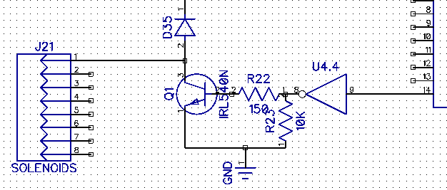
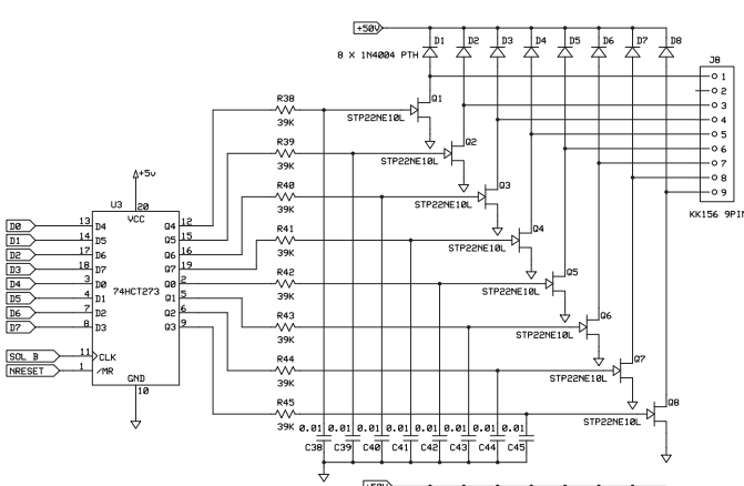
I'm trying to make a simple solenoid driving board for a pinball project, but running into problems. The basic requirement is to be able to repeatedly pulse 50V coils for about 100ms or less each time. I looked up the schematics for how some commercial boards do it, and found two nice examples:
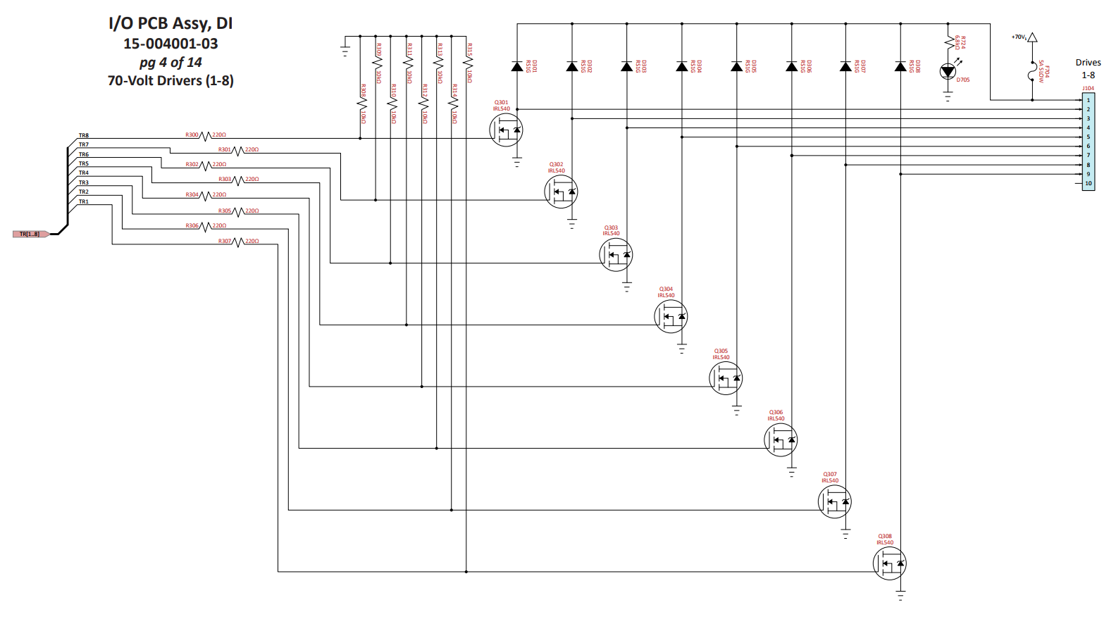
Based on these two designs I prototyped a similar single circuit with an IRL540N (equivilant to the STP22NE10l), a 10k pulldown, and a 160 ohm discharge resistor, controlled by the GPIO on a PIC32, but I found that within a few pulses (each a second apart) the fet becomes too hot to touch and soon begins to smoke.
Trying to find any other differences, I realized that the PIC32 was 3V, but these other boards were 5V (and the IRL540N doesn't really saturate till around 5-6V), so I looked for some other chip I could use to step up the voltage, and ended up with a 74ACT04N hex inverter (the inverter part doesn't matter, I just invert my signals from the PIC32). It has a low enough input voltage threshold that I can control it with the PIC32 while having it output 5V for the fet. However, although the fet lasted a bit longer, within a few pulses it'd still get too hot.
Of course, lowering the coil voltage or using a weaker coil makes it heat up less, but that's not really an option. Plus, the first circuit above runs at 70V, so there must be something else wrong if I can't manage at 50V.
I tried varying the resistance of my discharge resistor with various values between 150 (which is what I've seen recommended for mosfets) and 50k ohms, but that didn't make any difference.
I've tried comparing my 7404 with the latches used in the other designs, but I can't see any relevant differences. They're all (I think?) push-pull outputs, capable of 20mA+ (my 7404 can do more current than either of the latches), they operate on the same voltage...
Does anyone have any suggestions as to what the difference here might be?