Maker Pro
Maker Pro

LM317 2N3055 Variable Circuit Problems

So here is the million dollar question , why will the pot and lm317 go wrong when connected to a 10v 1.5a wall adapter or the main large 16v 15a transformer ???, the circuit is obviously working correctly with low current
It may or may not be working correctly just because there is no sparks or smoke. :) 
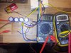
The little 9V is not capable of too much in the way of fireworks. But it's a start.

So before risking any more destruction, let's try to double-check that things are really working as they should. You have two multimeters, I see. Connect one to the LM317 output pin and ground to monitor its output voltage. Connect the second multimeter across the 220 ohm resistor to monitor the reference voltage. You can leave the transistors connected, but disconnect the fan load just to avoid running the little battery down.

Start with the pot at minimum. Both meters should read 1.25V (or thereabouts.) Turn the pot up and watch the output voltage increase, while the reference voltage stays the same at 1.25V. At some point the voltage will reach its maximum, which *should* be about 1.5V less than the battery voltage. If you turn the pot further, the output voltage will stay the same and the reference voltage will go down since the regulator has dropped out of regulation. If you do not get results like this, something may still be wrong.

------------------------------

I don't know if this will frustrate you or give you confidence, but I did an experiment earlier today. I found some stuff in my junk box where I was experimenting with power supply designs. I was able to fairly quickly lash up a reasonable copy of the circuit you are working from. A few differences, my two transistors are 2N3772s and my emitter ballast resistors are 0.22Ω instead of 0.47Ω.

The outcome of the experiment was that I was able to set it to 12V output and then push 10A into a load with the setup with no drama, other than the transistors getting quite hot of course. The regulation was poor as I expected it would be, the output dropped from 12.0V to 10.3V. The LM317 only needed to provide 161mA of drive current to achieve the 10A, so I got by without heat-sinking it.
LM317_007_12V_10A.JPG
 

(*steve*)

¡sǝpodᴉʇuɐ ǝɥʇ ɹɐǝɥd
Moderator
The reason those meters read differently is that one has a real diode test position (and reads the voltage drop) whereas the other indicates the appropriate resistance range to test diodes (and reads a "resistance").

Use the meter with the real diode test position.
 
20160829_035541.jpg Well I got out of bed to do this its 330am lol:p im that addicted to it at the mo, im not getting those results when pot is turned down one metre is showing 0.02 across the resistor its a 220 ohm resistor , the other metre on the v out pin is 1.27 , by the time the pot is turned up full with a bright led , one metre across resistor is 7.60 the other metre a on the v out pin is 7.75
 

Attachments

  • 20160829_035523.jpg
    20160829_035523.jpg
    323.6 KB · Views: 91
Last edited:
The yellow clip is on the orher side of the fixed resisror (adjust pin side) thats where I though It would make sense to be looking for the fixed voltage ??.. lol knitting lol mabe lol:) I did think about the other side if the fixed resistor but then the clip would be pretty much in the same place as the red clip so ?? Show me in a bread board please lol sorry guys:oops::rolleyes::oops::rolleyes:
 
Connecting the meter "across the fixed resistor" means connect the black probe to one lead of the resistor, and the red probe to the other. Dont' worry about polarity, the meter will just show a negative sign if you get it backwards.

Added:
Assuming the black lead of both meters were connected to ground and the reds were connected to the adjust pin and the output pin, those readings are OK. You were actually reading the voltage across the pot, as steve suspected.

And also assuming that you already knew the pot was reversed.
 
Last edited:
Lol to be honest I didnt think it mada a difference wires on the pot as I thought the pot is just a loop making a circuit and the varable resistor would still work the same just be backwards lol im still learning. Im out at the moment , when I get back later "a few hours" I'll go and do it correctly so I dont have to take up knitting lol "bluejets you cheeky boy" lol:):):)
 
the varable resistor would still work the same just be backwards lol im still learning.
That is essentially correct, but one does expect "minimum" to be associated with counter-clockwise and "maximum" with clockwise. So that when you say turned the pot "down", we know what you mean.

I know is not as much fun as wrangling wires and smelling magic smoke, but I do suggest that you go back and read my post #99 from yesterday. Read it over and over until it makes sense. Ask questions until it does. You need to know and understand *some* basic theory, or your projects will always be difficult and sparkly in a bad way. Either that, or it's knit one purl two.
 
The pot is now correct (+, -)so we don't
get confused sorry about that:) , this is the reading with the right side meter ( + ) probe "yellow clip" connected to the 220 resistor black probe connected to the Middle pin of pot , the pot is turned down 1.27v on out put.20160830_012804.jpg
The second pic is pot turned up full the volts dropped on the meter connected to resistor , can i give up the knitting now;)20160830_012822.jpg
are you going to tell me to ceep on knitting because this is still wrong lol .:(
 
Yes , well 7.4v before the decline but that is close enough with these cheap meters right . And I went back to the algebra modemhead sent me to understand with the explanation diagram to work out how to do the calculations CLICK "so far anyway" very good explanation , I did the math on a calculator as I was reading it so I could 100% know what and how I was working out , thanks for that one , the calculator gives a longer number but the numbers I was looking for were there , i remember heavans saying about three significant numbers , all of you guys should meet up you could probably create/invent somthing realy good make $$$$$$$$ , im glad I came on this site you are all teaching me loads even tho I am making mistakes on the way , I do get a bit confident and smoke bits n bobs but it is all part of my practicle learning im giving myself the hands on approach while I ask you guys whats going on with what I am doing so i can understant it hands on , I mean look at the start of the thread I didn't even know the pins on the 2n3055's ... thanks for having the patience to help me learn :rolleyes:
 

(*steve*)

¡sǝpodᴉʇuɐ ǝɥʇ ɹɐǝɥd
Moderator
Yes , well 7.4v before the decline but that is close enough with these cheap meters right .

The actual point at which it happens depends on the load and the input voltage.

You must have a reasonably new 9V battery, and you also have as close to zero load as is possible.

It's all ok :)
 
New battery steve, I took your advice and bought 9v pp3 to do this with and the connector to plug it into to make it easy to power the board , the lowest thing I got to use is the 10v 1.5a wall adapter , I was getting a bit fed up with smoking the 317's and checking everything is in the right place over and over finding no explanation why the smoke , what should I test next ? Im a bit wary of connecting it to the big transformer "it won't like it lol"
 

(*steve*)

¡sǝpodᴉʇuɐ ǝɥʇ ɹɐǝɥd
Moderator
In theory of it works here it should also work from your transformer.

But before you try it again, can you measure the voltage at the filter caps of this supply and let us know the voltage.
 
Well bob I been through a few to burn the pots20160830_191936.jpg , I still think it will smoke when I connect it to the big boy Iit has every other time , but first Steve 9.3v on the smoothing caps off the 9v battery , adjusting the pot makes a bit of difference "there is a led connected" i have 14+ volts dc out of bridge rectifier i thought you may ask so i checked that too , it is not connected to the board yet , just out of interest i clicked the meter over to ac while i was connected to the bridge rectifier it was 30+ ac is that a problem? Or normal?20160830_190150.jpg
20160830_190418.jpg
 
Yes, that is a problem, you should not be reading 30V on the AC scale.

Don't connect that to your circuit until it has been diagnosed.

Bob
 
Top