Maker Pro
Maker Pro

I'm Back- sort of

The sound is very low in volume compared to the Youtube clip. At a proper volume, it should pump out the same punch as in the video. By the way, I used the TL081 (which has the same pin settings as the 4558D).
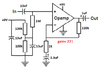
No. The pin numbers on a TL081 opamp are completely different to a 4558 dual opamp.

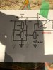
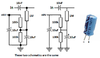
Your Google Cloud sounds had no low frequencies maybe because a capacitor value is much too small.
Please post your latest schematic with all the resistor and capacitor values.
 
I'm not sure if I should create a new thread for this question.

I am wondering if there is any way an electronic circuit can be designed to achieve the following:

Below you will find a sound file of me playing a guitar chord. You will note that the sound oscillates between being on and off.

Certain Gibson Les Paul guitars come with a kill switch. This is a toggle switch that sits high up on the guitar's face that enables you to completely kill the sound. I have linked to a sound file below, in which I was toggling the kill switch on and off.

I am wondering if there is any way to build an electronic circuit that would achieve the same thing. in other words, at the push of a button, or the throw of a switch, have the sound toggle on and off. But have it switch on and off in an automated way.

So, in the context of an overdrive pedal, have that feature built in somehow.

Is this doable?

Here is the clip:
https://drive.google.com/file/d/1SnkS7Ah64KRNgsSQ_jUvFrBYQJuObyI9/view?usp=sharing
 
Your opamp had no DC input bias voltage.
Your 220nF capacitor value reduced the levels of all low frequencies at 727Hz and below.
3.3uF passes all guitar frequencies because it is 15 times more.
Make the preamp like this:
 

Attachments

  • preamp.png
    preamp.png
    29.2 KB · Views: 8
A kill momentary pushbutton would be wired with a shielded audio cable parallel with the guitar pickup.
A pushbutton with gold plated contacts (very low current rating) works reliably for audio and costs the same as a pushbutton with silver plated contacts (high current rating) that get corroded (because a high current burns away the corrosion) and fail in a few months.
 
I will likely start the new build today.

in terms of the kill switch functionality, what I was wondering about is a way to have it go on and off electronically. In other words, you hit the switch once and it begins automatically going on and off until you hit the switch again.
 
An electronic tremolo on-off can be done with a 555 oscillator driving a 2N7000 Mosfet. Each time the Mosfet is turned on it shorts the signal to ground.
You probably need a pot to set the speed of the pulses and maybe another pot to set how much the signal level is cut for each pulse.
 

Harald Kapp

Moderator
Moderator
1. 4.56
2. 4.58
3. 4.15
4.0
5.4.15
6. 4.57
7. 4.57
8.9.03
What? Volts, Bananas, Amperes, Millivolts, Apples?
Please do provide units for your measurements.
Also what should "8.9.03" mean? pin 8 at 9.03 V or pins 8 and 9 at .03 V? Help us help you by making clear statements. Your list would be much easier to understand if it were formatted e.g. like this (just an example):

pin: voltage
2: 4.58 V
3: 4.15 V
4: 0 V
5: 4.15 V
6: 4.57 V
7: 4.57 V
8: 9.03 V
 
I think I am second guessing myself.

Please have a look at the attached schematic that I marked. I am assuming that the 10uF capacitors that I have arrows pointing downwards from, connect to ground- correct? They don't necessarily have to connect to each other, at the point that I circled right? I suppose it does not matter, as the 100K resistor and the two 10uF capacitors that I put arrows to, all go to ground.
 

Attachments

  • IMG_5094.jpg
    IMG_5094.jpg
    217.5 KB · Views: 4

bertus

Moderator
Hello,

The two capacitors and resistor are all connected to ground.
The circled part could be a connection point.

Bertus
 
Yes, the ground wire (or 0V wire) of a modern electrolytic capacitor is marked with an arrow or thick line. A long time ago the + wire was marked with a "+" instead which is why the + is marked in modern schematics.
 

Attachments

  • capacitor grounds.png
    capacitor grounds.png
    47.6 KB · Views: 2
The good news is that this was another successful build, in the sense that I am getting sound.

The same problem seems to be in play however. Not very much volume.

Now, if I use the distortion dial on the amp itself and turn it up, I get lots of sound. But this is not proper as I am feeding distortion from the op amp, into distortion inside the guitar amp (which has its own distortion circuitry).

It's late so I can't try this now, but perhaps I should try plugging into my Fender Hotrod amp or my Fender Mustang. But my guy tells me that it ought to work with any amp.

Any thoughts?
 
Update:

My curiosity got the better of me, and so I got up and tried it with a Roland Cube amp- which is a little bigger that the desk top one Huge difference!!! It works!!!

I don't know why the Orange amp was not reacting as well. Maybe the circuit within the orange amp is such that you have to give it a little internal guitar amp distortion, before it will apply any significant volume.

However, because the Roland Cube can be used as a busking amp, it likely is more substantively built.

In any event, rest assured, mission accomplished!!!

Thanks to AG, Bertus and Harald for all the coaching! Now, I will move on to pots and diodes.

P.S. I'll record a sample tomorrow and post it. Requests?
 
I am thinking that perhaps the previous builds may have worked too. I have always used the orange amp to test as it is so small and convenient. I never thought to suspect it as being an issue. My apologies. The good news is that it works!!!

To continue on, should I follow the original schematic for the pots and diodes, or is there something about the revisions that require an adjustment? Also, is it possible to install a small toggle switch on one of the legs that run to the diodes that would enable me to include or not include the diode circuit in the sound, or is that accomplished by turning down the pot that is part of the diode circuit? If possible, I want to be able to drive the output with and without the diodes.

Lastly, I may need help figuring out how to rig this to a typical stomp box switch that one stomps on and off with his foot. I have many of those switches but have never hooked one up.

Thanks for hanging in with me. I am learning a lot albeit sometimes through painful unexpected things happening such as the nature of my little Orange amp.
 
The output of an opamp is about 7V peak-to-peak when the battery is 9V and there are no diodes in the negative feedback.
With the diodes the output of the opamp is about 1.2V peak-to-peak that produces much less loudness.
Since the diodes bypass the gain pot and reduce the gain in addition to reducing the output level, the high gain of 221 times without the diodes produces massive opamp output clipping distortion.
 
AG....I am not sure I follow what you are trying to tell me,. But this is what I think you're saying.

If I built in such a switch and flipped the diodes on, the sound would not be as loud, but the color and nature of the distortion will change (for the better I assume).

If the switch by passes the diodes, it is all op amp distortion, whihc will be considerably louder with a different characteristic.

Yes?

Another question:

I have the following diodes available to me:

1N4148

1N914

LEDS

I also have a bunch of other diodes that came in a variety pack of sorts, but I can't tell if they are appropriate for these types of circuits. They seem to have larger canisters,

In time, I will likely set up a breadboard and try out different combinations. For now however, does anyone have a recommendation as to which I should use in this circuit?
 
Top