Maker Pro
Maker Pro

IGBT ignition coil driver

Hi all,

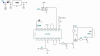
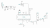
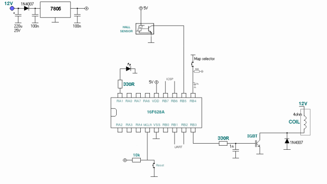
I'm making a programmable ignition module for a very old scooter and have made the below schematic however I've found that with a multimeter in place of the coil the voltage switches correctly and I see 12V however when I put the coil in place the voltage stays at 0V.

The IGBT is this one: HGTP7N60C3D

Any ideas what I'm doing wrong? I'm not very good at the electronics side of things unfortunately.

Thanks for any advice!

schematic_v2.png
 
Last edited:
You are looking at the right thing, the threshold voltage is where the device just starts to conduct. There will be enough current to drive a voltmeter but not to do any useful work. The data sheet shows a graph giving the gate votage necessary for the required output current.
 
You want a voltage follower or common collector circuit. Right now when the transistor is off the gate will be held high. http://en.wikipedia.org/wiki/Common_collector
Notice how Vout is on the emitter side with the resistor connected between Vout and Gnd

I don't think you will need the cap from base to ground, it will just delay the turn off time of the BJT.

Ah yes, you're right, silly me.

Thanks guys for the help. I'll give it a shot after work tonight.
 

(*steve*)

¡sǝpodᴉʇuɐ ǝɥʇ ɹɐǝɥd
Moderator
That transistor can't be turned significantly on -- it won't work any better than the original. I'll see if I can find something for you. I'm not at home so I can't draw anything for you.
 

(*steve*)

¡sǝpodᴉʇuɐ ǝɥʇ ɹɐǝɥd
Moderator
Something like this would be better

attachment.php


The two 100 ohm resistors represent your load (it's not your actual load, clearly).

the 40Hz signal is a square wave going from 0V to 5V and represents the output of your PIC.

The output swings to within a couple of volts of the supply rail and can sink/source significant current. I would recommend a gate resistor to limit the current.

The resistor values shown are just values I pulled out of my head, the values you might use depend on the current you want to sink/source and the gain of the transistors.
 

Attachments

  • Driver.jpg
    Driver.jpg
    12.8 KB · Views: 3,604
OK, I'm confused, which is totally not difficult I admit!

Why is there two resistors representing the load? And how do I implement this with the 5V & 12V circuits?

And s the IGBT no longer used? I thought this would be required given it's an automotive ignition coil?
 
OK, I'm confused, which is totally not difficult I admit!

Why is there two resistors representing the load? And how do I implement this with the 5V & 12V circuits?

And s the IGBT no longer used? I thought this would be required given it's an automotive ignition coil?

Or can the whole circuit simply be thought of as 12V but the square wave still represents the 0-5V output of the PIC?
 

(*steve*)

¡sǝpodᴉʇuɐ ǝɥʇ ɹɐǝɥd
Moderator
this may be easier to follow. I've inserted a mosfet because the package doesn't have a igbt

attachment.php
 

Attachments

  • Driver2.jpg
    Driver2.jpg
    10.8 KB · Views: 3,493
Ahhh, OK. I get it now.

I've integrated that into my schematic, and will test it out now.

Thanks so much for the help!

attachment.php
 

Attachments

  • schematic_v3.png
    schematic_v3.png
    29.8 KB · Views: 5,097
OK, I've implemented the above schematic and it's not quite working.

With just the multimeter for load everything reads correctly. However once I include the coil the voltage drop across the coil is only 0.45 volts.

Any ideas?
 

(*steve*)

¡sǝpodᴉʇuɐ ǝɥʇ ɹɐǝɥd
Moderator
Disconnect the connection to the PIC, and tell us the voltage at the gate of the IGBT and across the coil. Then connect it to +5V and repeat the readings.
 
Disconnect the connection to the PIC, and tell us the voltage at the gate of the IGBT and across the coil. Then connect it to +5V and repeat the readings.

Sorry, my bad. I got the base and collector on the IGBT confused. I'm an idiot.

Now I do get the odd spark from the coil, so I'm getting somewhere!

However something is still up. I get one spark and then I suspect the PIC is crashing; it starts getting warm and stops responding to inputs. The IGBT also gets _very_ hot.

I'll recheck the circuit now incase I've stuffed up again.
 

(*steve*)

¡sǝpodᴉʇuɐ ǝɥʇ ɹɐǝɥd
Moderator
There may be a few things going on.

Firstly, the electrical noise from the could may be getting back to the PIC and confusing it. I would suggest that your 5V regulator be protected from spikes. A small series resistor and n 18V zener placed before the 220uF capacitor would help.

If you're drawing sparks off this coil, then it will generate huge spikes if the spark isn't drawn from it. These may well exceed the avalanche voltage of the IGBT.

Connect (temporarily) a reverse biased diode across the coil (capable of handling the full coil current) and see if this reduces the lockups and IGBT heating.

Damage to your IGBT is also a possibility.
 
There may be a few things going on.

Firstly, the electrical noise from the could may be getting back to the PIC and confusing it. I would suggest that your 5V regulator be protected from spikes. A small series resistor and n 18V zener placed before the 220uF capacitor would help.

I'm guessing I've done it wrong as I'm not getting any 5V?

This is the schematic.
attachment.php


Thanks for your help!
 

Attachments

  • schematic_v3.png
    schematic_v3.png
    31.7 KB · Views: 2,814
Top