Maker Pro
Maker Pro

HOW TO ID-- A 12 VOLT ZENER DIODE --ONE WATT --

Hi ----
The same old problem -revisited ----trying to find identify a Zener diode from hundreds of look-alikes
dead ringers --
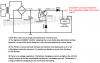
A battery charger circuit ----using TIP 122 power transistor ---
requires a rugged Zener diode voltage regulator -----

--tried a tiny glass orange diode (cannibalised from old TV circuits )---and many other look alikes
Zener symbol clearly shown on PC board ---but it fried /burnt up --went black --
so obviously --too low wattage --

but as a bush dwelling amateur -----cannot unravel those tiny numbers /codes on those nasty little
glass zeners ---huge mag glass ---applied ----those numbers are hard to read --/confusing -even when removed with difficulty from said Old pc boards/mother boards etc --plentiful supply !

As I have no idea what or how a 12 volt one watt Zener Appears (resembles std glass diodes )----and I do not want to wait 6 weeks to import the diode ----
All I really want is to learn how to IDENTIFY the said ZENER--DIODE --already attached or removed
from old PC boards--
maybe asking a awkward question ----
AS--those numbers/codes are confusing --is there a list /guide /chart --available
that explains those tiny mysterious numbers --?

Eyesight at 70 not too good ---so any help will be appreciated

thankyou ---retired hunter/taxidermist --amateur circuit builder
Zendode
 

(*steve*)

¡sǝpodᴉʇuɐ ǝɥʇ ɹɐǝɥd
Moderator
Get 2 9V batteries, a 10k resistor and a multimeter.

Connect the negative of one battery to the positive of the other.

Connect one end of the resistor to one of the unused battery terminals.

Using your multimeter on a DC voltage range, connect the probes to the other unused battery terminal and the free end of the resistor. The meter should read something close to 18V. If it reads -18V, swap the meter leads around.

Note place a diode across the meter probes. One way they'll read a low voltage (under 1V). The other way, if they read less than 18V then the diode is likely to be a zener diode. The voltage you see on the multimeter is the zener diode voltage.
 
Many Thanks Steve---
will attempt your 2x 9v battery idea --
what diode do I use --if I am not sure what a Zener even looks like ?

and most important of all ---how do I determine the WATTAGE range ?
The battery charger circuit shows a ONE WATT 12 VOLT zENER -IS required !
on the middle leg of TIP 122 transistor --and earth----
( the tiny glass diode I tried ---got red hot & burnt out in less than a minute!
so obviously wattage was way too low ?

ONE WATT / ? how to find one watt written in code on such a tiny orange glass
diode is near impossible --surely --like colors on a resistor or microfarads on a capacitor
--there should be some easily referenced code # stamped on the diode --
( I can decipher only vague letters / numbers on the micro glass surface
even a giant magnifying glass ---shows weird odd numbers --)

ok let me try the voltage plan you suggest ---to start with ---to find 12 volt --zener -
but it will burn out again ---if wattage is too low surely?

Many thanks --appreciate -
Zendode--
 

Attachments

  • ZENER DIODES-HOW TO  IDENTIFY--12 VOLT -ONE WATT --IN OLD TV CIRCUIT BOARDS 008.JPG
    ZENER DIODES-HOW TO IDENTIFY--12 VOLT -ONE WATT --IN OLD TV CIRCUIT BOARDS 008.JPG
    224.8 KB · Views: 638

(*steve*)

¡sǝpodᴉʇuɐ ǝɥʇ ɹɐǝɥd
Moderator
Well, the first thing is to determine if any are zener diodes.

The small glass diodes, if they are zener diodes are typically 400mW or so. 1W zener are a little longer and almost twice the diameter. But remember that the are many package types.

If you can make out what is written on the diodes you can google for them.

For example, the diode in the middle (black with short leads and a silver band) has the letter N and the digit 4 visible. I suggest that if you look carefully you'll see that it has 1N4001 written on it. (It also might be 1N4002, or similar). These are rectifier diodes, not zener diodes.

Does are polarised. The diode that got really hot may have been placed in the circuit back to front. If it's not a zener diode then it won't get hot, but it will also probably not work in the circuit either.
 
The wattage is inherent in the little number on the diode.
I've found that a cheap 4x loupe helps a lot when trying to read those numbers.
 

(*steve*)

¡sǝpodᴉʇuɐ ǝɥʇ ɹɐǝɥd
Moderator
I've just got a clip-on macro lens for my current phone. It cost less than $5. It's not great quality, but in the centre I can easily use it to read tiny writing on small devices.
 
I've just got a clip-on macro lens for my current phone. It cost less than $5. It's not great quality, but in the centre I can easily use it to read tiny writing on small devices.

wow !! ---those 2 X9V BATTERIES ---10 K RESISTOR idea /method is a killer !! works SUPERBLY --
GOT 4 .5 VOLTS ON ONE glass diode ( tiny )
5 .8 volts -7 volts on others --some read 2 -3 volts only !

proves some are Zeners ---the others I knowq are IN 4007 and 4001 STD rectifier diodes
not Zeners --

YOU SAY -- zENERS are slightly LONGER & FATTER than ordinary glass diodes?
ok ---all these are tiny --same size ---
now I have to search for a fatter /slightly longer ZENER GLASS DIODE ?
OK ---- but the wattage issue remains ---
or shoud I simply try them all in place ? --till they burn out /turn black ?
(trial & error)
my eyesight is hopeless even with a powerful macro lens on camera --
tried foto close ups ---still cannot decipher those codes /numbers
but the 4001 --4007 black /silver bar diodes I have eliminated

now to search a mountain of circuit boards for that ONE watt fat bug diode?

Can you give me a schematic drawing or sketch ---of that 2 x 9 volt battery system ?
really works well ---however I am not sure if I got it right --
ROUGH sketch will be fine --if u can post it for me ?
Then
I can make up a Zener circuit tester --permanent --based on your idea

most grateful --
never stop an old dog from learning new tricks from other masters!
regards
zendode--(Zululand)
(burnt this 7412 IC on initial battery charger circuit --(stupidly crossed "+ & neg )
so I had to revise ---use the TIP 122 circuit ----backup ----
but different circuit---- the evil ZENER had to be found!!
 

Attachments

  • BATTERY CHARGER --USING 7214 CONTROL IC 002.JPG
    BATTERY CHARGER --USING 7214 CONTROL IC 002.JPG
    227.7 KB · Views: 272
I think your TIP122 with a zener diode connected to its middle leg (its collector) and ground applies the entire input power supply to the zener diode to burn it out.

I found a charger using a TIP122 and a 12V zener diode. The circuit voltages are wrong so it will not work and I show why your zener diode burns out:
 

Attachments

  • TIP122 charger.png
    TIP122 charger.png
    147 KB · Views: 978
ZENER DIODES--GLASS--- NEXT TO std diode.JPG
I think your TIP122 with a zener diode connected to its middle leg (its collector) and ground applies the entire input power supply to the zener diode to burn it out.

I found a charger using a TIP122 and a 12V zener diode. The circuit voltages are wrong so it will not work and I show why your zener diode burns out:

WOW ---Audioguru ----
you certainly got the EXACT TIP 122 circuit I have made!
--What I did --to get 13 .4 volts -----output ---

was
1 --replace the ZENER DIODE on middle leg of TIP transistor
with large rectifier black diode ( IN 4007 or similar )
2 ----removed the LED ---& I K ohm resistor in series ---

3 ---Voila ---13 -4 ---13 .7 Volts DC ----OUTPUT !
no idea why this huge I cm long heavy duty rectifier works ---
but as I could not find a one watt Zener ---I took a risk ---

no -more overheating --steady output ----battery now fully charged!
if you can figure out this freaky scenario --I would welcome your assessment

( the circuit I made is EXACTLY same as your posted schematic !)

What I still have NOT learnt ---(shamefully)--
is the difference between Zener and ordinary junction diode !
terms such as avalanche voltage " & reverse BIAS serve only to confuse /baffle
me all my life --
(transistors are easier to grasp ===so are all the rest (capacitors /induction coils etc )

but Zener diodes are still a mystery ---
here are foto I took just now ---
ie ---a Zener diode (symbol clear ) right NEXT to a ordinary SAME SIZED glass diode !
cannot see the difference --except the indecipherable numbers --on each orange glass surface ---
BUT I will remove them from the old TV board ---
and try again --to READ those microscopic numerals --
great learning fun --------got to get this right !

All my guitar amps I built --work very well with a lot of help from this forum --2 years ago
( usedTDA 2006 IC /s )
now those amps did not require any Zeners --just good old IN 4001 /4007 std black rectifier diodes --

one day ---someone will create a ANIMATED PC generated video of electrons
flowing through a ZENER diode --7 WHAT the heck goes on inside that enigmatic
object !!---a visual moving teaching video would explain more than a thousand words could

Steve has helped me enormously ----
a schematic drawing would be extremely helpful in seeing how to test a Zener voltage
(picture paints a thousand words --simplifies jargon filled complex explanations )

Appreciate all the great sage advice ---
here are fotos
 

Attachments

  • ZENER DIODE--GLASS--- NEXT to std diode -look same.JPG
    ZENER DIODE--GLASS--- NEXT to std diode -look same.JPG
    319.9 KB · Views: 1,002
Last edited by a moderator:
You connected the base and collector pins of the TIP122 backwards so that it is not a darlington transistor anymore. That is why the zener diode burns out. I showed a photo of the labelled pins as shown in its datasheet.

The big black diode you added does nothing since it is not a 12V zener diode.

Here is how I think you changed it:
 

Attachments

  • TIP122 charger more errors.png
    TIP122 charger more errors.png
    113.5 KB · Views: 838
No, I said that those the size of the small glass diodes are typically 400mW, with 1W zener diodes being larger.

Sincere apologies Steve --I meant one watt ----you said bit bigger ---
OK voila !!
searching carefully ---I found 2 slightly broader in girth ---glass diodes with odd markings -
(see fotos)
Astounded! when tested your method ---
they show TWO voltages --one way -then the other --precisely as you indicated!
(I used a 12 volt battery with 15k ohm resister )no 9 volt available right now )

so finally its dawned on me --reverse voltage and forward voltages on a Zener
are evident --ie 12 '7 volt --one way
5 '6 volt in reverse !! wonderful ---NOW I get it
( a standard diode look-alike ONLY shows one way traffic --typical diode behaviour)
and a Zener has two readings both ways ---Magic ---
Finally ---taken so long to understand Zeners

ok --really appreciate the help ---
foto shows the 2 fatter diodes may be one watt Zeners--found quite a few
-careful observation shows these bigger diodes have 2 bright yellow "bands "
separated by a thin black band---lot different color than std glass diodes as well as size -
now I am much wiser !
hopefully they are one watt !--will try to connect CORRECT way round to the TIP mid leg
---very grateful ---
Zendode
 

(*steve*)

¡sǝpodᴉʇuɐ ǝɥʇ ɹɐǝɥd
Moderator
Zener diodes are used reverse biased because the breakdown voltage is the thing they're made for.

The forward voltage should be about 0.6V, not 5.6V though.
 
Zener diodes are used reverse biased because the breakdown voltage is the thing they're made for.

The forward voltage should be about 0.6V, not 5.6V though.

So now I am again in the dark ---
if forward volts are 5.6 --reverse voltage is what/?12 VOLTS ?

AND how come I connected the TIP leg pins wrong ?
I followed the schematic exactly as it was shown ---
middle leg to zener -----
left leg receives volts from rectifier diode bridge --
right leg is output (pos) to battery --
how can all this be wrong ? --
I get 11 .5 volts only at output --when I connected the new "fat zener to TIP 122 mid leg

so maybe the Zener is less than 12 volt ---
but at least its ONE WATT as you described --
so I will search for a 12 volt zener ---
but how to find 12 volt reading --?
if I use your method 0--then 12.5 volt one way
and 0.5 volt in reverse ?
that gives 12 volt ? ---
looks like the fat diode I found was only 6 -8 volts --
WHAT a mess --back to the drawing board --totally lost !
 

Attachments

  • FINALLY --BIGGER ZENERS FOUND --COMPARISON 005.JPG
    FINALLY --BIGGER ZENERS FOUND --COMPARISON 005.JPG
    168.5 KB · Views: 468
You connected the base and collector pins of the TIP122 backwards so that it is not a darlington transistor anymore. That is why the zener diode burns out. I showed a photo of the labelled pins as shown in its datasheet.

The big black diode you added does nothing since it is not a 12V zener diode.

Here is how I think you changed it:

OK ---Thankyou Audioguru ---
if I connected the TIP incorrectly --
can you show me how to connect another TIP 122 ( I have many spares)
I have found a fat one watt zener glass diode ---but not sure what voltage --reads 12 v one way --4-5 voltsv the other way ---
is this 7 or 8 volt Zener ?
I am now so confused ---
but you were correct ----output of the charger fell to 11 '5 volts ---
when used a NEW 9v BATTERy in my multimeter ---
( old flat battery I am told --gives inflated /distorted readings --(13-14 volts)
now its down to 11 .5 VOLTS -- should be 13 ,6 volts for charging properly?

cannot understand how that TIP 122 WAS cross wired --
I assumed as the shematic showed ---to connect middle leg to zener --
left leg to input from bridge rectifiers ----right leg ----out put to battery !
so that was incorrect ?
can you show me the proper connections /configuration ?--ie a diagram

appreciate all your sage advice ---
(apologies ) still learning -----but I refuse to give up !
regards -- Zendode
 

hevans1944

Hop - AC8NS
Try looking at the diodes on this page. They are ALL 1W zener diodes and they are ALL the same physical size.. However, the amount of power a zener diode dissipates depends on the product of the zener voltage and the current you allow to flow through the zener. For the simple circuit using a TIP122 connected as an emitter follower, the 270 ohm resistor provides current from the 19.4 V filtered supply, dropping (19.4 - 12 ) V or 7.4 V across the resistor. This means (7.4) / (270) A of current through the resistor and the zener since they are in series. That works out to 0.027 A. So the power dissipated in the zener will be (0.027) (12) = 0.329 W.

The power dissipated in the resistor will be (0.027) (7.4) = 0.203 W. So for this circuit, a 1 W zener and a 0.5 W resistor will work just fine. Note that some current will also be drawn at the base of the TIP122 as the transistor provides current to the load on its emitter, but with any reasonably large transistor beta and a limited amount of current in the load, this base current will not significantly affect the power dissipation calculation.

If the circuit is used to charge a battery, the emitter voltage will be two base-emitter junction voltage drops (about 1.4 V) below the voltage applied to the base because the TIP122 is a Darlington-connected transistor-pair. It is unfortunate that this base-emitter voltage drop is a non-linear function of both temperature and collector current, but without a more sophisticated circuit, it is what it is.

The power any diode can safely dissipate depends on how the heat produced by that power escapes to the environment and the thermal resistance of that path. For any given power, the goal is keep the junction temperature of the diode less than a specified maximum, usually 200C for silicon junction didoes.

For a glass or epoxy encased diode, power dissipation is mainly from the base of the semiconductor die chip soldered to one of the diode leads, and the heat is conducted from the chip to the lead to the copper foil on the circuit board. Some heat is also conducted to the other lead, but that depends on how it is attached to the die chip. And finally some heat is conducted to the glass or epoxy case. Both glass and epoxy are poor thermal conductors, i.e., high thermal resistance but you still want to have them maintained at near ambient temperatures like 25C.

As for how zener diodes work... take a look at the diode I-V curve shown below. This curve describes BOTH zener AND regular diode conduction. The ONLY difference is zener diodes are DESIGNED (by how their junction is doped) to break down and conduct without failure when reverse biased at greater than their zener voltage AND the current is limited (with an external resistance) to be less than their maximum current rating. Regular diodes usually fail when their reverse breakdown voltage is exceeded, even if current-limited by an external resistance.

diode8.gif
 
You connected the base and collector pins of the TIP122 backwards so that it is not a darlington transistor anymore. That is why the zener diode burns out. I showed a photo of the labelled pins as shown in its datasheet.

The big black diode you added does nothing since it is not a 12V zener diode.

Here is how I think you changed it:

Audioguru ----
you were right on ---I messed up big time ! How I could connect the middle pin (collecter )
to the Zener --is plain blind stupidity --forgot completely how I made audio amps from this TIP122-many years ago !( without a problem )

So I had to reconfigure the connections ----I got so wrong !
The left pin is the base and the right pin the emitter -Center pin is the collector(output)---I am a damn idiot !
Ok have turned it all around --correctly --
You were right --this circuit is horribly wrong ---I get 17 V dc Out!!-but why was it posted for all to use ?

Anyhow --still cannot find a 1 Watt Zener 12 volt --however I did find a grey zener -
with 8v6 stamped on it ---( 8.6 volts ) REVERSE reads 4 .8 volts -no wattage known--tried it in place----no difference --
So--I have given up on this charger ---
will order the correct 7812 ic volt regulator that burnt out ---from my original successful battery charger --that circuit worked well ( until I carelessly connected the battery in reverse ! Bang --goodbye IC !--(Red hot )
--no more nasty Zeners required --!Still not sure how they work -
breakdown voltage and reverse bias are way beyond me --that's quantum physics -
All I want is a working battery charger --will try other circuits that DO work !
Many thanks ---
Zendode
 
Try looking at the diodes on this page. They are ALL 1W zener diodes and they are ALL the same physical size.. However, the amount of power a zener diode dissipates depends on the product of the zener voltage and the current you allow to flow through the zener. For the simple circuit using a TIP122 connected as an emitter follower, the 270 ohm resistor provides current from the 19.4 V filtered supply, dropping (19.4 - 12 ) V or 7.4 V across the resistor. This means (7.4) / (270) A of current through the resistor and the zener since they are in series. That works out to 0.027 A. So the power dissipated in the zener will be (0.027) (12) = 0.329 W.

The power dissipated in the resistor will be (0.027) (7.4) = 0.203 W. So for this circuit, a 1 W zener and a 0.5 W resistor will work just fine. Note that some current will also be drawn at the base of the TIP122 as the transistor provides current to the load on its emitter, but with any reasonably large transistor beta and a limited amount of current in the load, this base current will not significantly affect the power dissipation calculation.

If the circuit is used to charge a battery, the emitter voltage will be two base-emitter junction voltage drops (about 1.4 V) below the voltage applied to the base because the TIP122 is a Darlington-connected transistor-pair. It is unfortunate that this base-emitter voltage drop is a non-linear function of both temperature and collector current, but without a more sophisticated circuit, it is what it is.

The power any diode can safely dissipate depends on how the heat produced by that power escapes to the environment and the thermal resistance of that path. For any given power, the goal is keep the junction temperature of the diode less than a specified maximum, usually 200C for silicon junction didoes.

For a glass or epoxy encased diode, power dissipation is mainly from the base of the semiconductor die chip soldered to one of the diode leads, and the heat is conducted from the chip to the lead to the copper foil on the circuit board. Some heat is also conducted to the other lead, but that depends on how it is attached to the die chip. And finally some heat is conducted to the glass or epoxy case. Both glass and epoxy are poor thermal conductors, i.e., high thermal resistance but you still want to have them maintained at near ambient temperatures like 25C.

As for how zener diodes work... take a look at the diode I-V curve shown below. This curve describes BOTH zener AND regular diode conduction. The ONLY difference is zener diodes are DESIGNED (by how their junction is doped) to break down and conduct without failure when reverse biased at greater than their zener voltage AND the current is limited (with an external resistance) to be less than their maximum current rating. Regular diodes usually fail when their reverse breakdown voltage is exceeded, even if current-limited by an external resistance.

diode8.gif

Thankyou so much for all this info Hevans !
I still cannot IDENTIFY a one watt Zener 12 volt --!
Your lesson on its function /characteristics etc is way too complex -
but I do understand a bit here & there --"reverse breakdown voltage & forward operating region I will never grasp ---way too abstract ----
all I want is a foto of a Zener one watt 12 volt ---
so I can find them easily on old PC boards --
DIODES I learnt 50 yrs ago --are one way valves --the junction of silicon /germanium
& impurities --allow electrons to flow in one direction --to give '"PULSE DC --FROM
AC --- I e the std diode partly rectifies AC --( CUTS out neg part of sine wave )
-but how zENER works in D C bATTERY charger is a huge mystery --for me -!

All I need right now --is to find a simple charging circuit (sans Zener nightmare !)
most grateful for your kind analysis --
really appreciate ---will save the above to files --to study later ---
its a lot to absorb ----but very valuable info ---I never had the chance to study before--

now its hard to grasp at my age ---but will soldier on !
best regards from the backwoods --Zendode
 
OK ---Thankyou Audioguru ---
if I connected the TIP incorrectly --
can you show me how to connect another TIP 122 ( I have many spares)
I have found a fat one watt zener glass diode ---but not sure what voltage --reads 12 v one way --4-5 voltsv the other way ---
is this 7 or 8 volt Zener ?
I am now so confused ---
but you were correct ----output of the charger fell to 11 '5 volts ---
when used a NEW 9v BATTERy in my multimeter ---
( old flat battery I am told --gives inflated /distorted readings --(13-14 volts)
now its down to 11 .5 VOLTS -- should be 13 ,6 volts for charging properly?

cannot understand how that TIP 122 WAS cross wired --
I assumed as the shematic showed ---to connect middle leg to zener --
left leg to input from bridge rectifiers ----right leg ----out put to battery !
so that was incorrect ?
can you show me the proper connections /configuration ?--ie a diagram

appreciate all your sage advice ---
(apologies ) still learning -----but I refuse to give up !
regards -- Zendode
I think you are using a circuit from a 3rd world country designed by someone who knows little about electronics.
You did not see the photo I posted of the TIP122 pins. The middle leg is the collector but the schematic of the circuit shows the zener diode connected to the base, not the collector. Look at my copies of the schematic where I labelled the pins since you do not know anything about transistors.

A 12V zener diode limits the voltage across it to 12V when reverse biased and is an ordinary 0.7V diode when forward biased. A 12V lead-acid battery is charged at about 13.8V to 14.4V. This horrible circuit has a maximum output of only about 10V.
 

Attachments

  • transistor.png
    transistor.png
    40.1 KB · Views: 312
Top