Maker Pro
Maker Pro

Help with Circuit board needed asap

Hi

New to this forum, so first I want to say hello to you all and introduce myself. My name is Paul from Kent and I urgently need some help and advice with a circuit board problem. Now I'm not a electronics geek, just a handy guy who can turn my hands to most things.

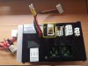
I bought a motorhome last year for my family and discovered it had major water damage, so spent a year renovating it, loads of work. Almost finished but recently discovered that the main 12v/240v Power Management and Charging unit as been bodged by previous owner (owners) and as melted housing connectors, and modification made by soldering wires directly to circuit board.

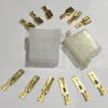
I have took the unit apart to have a closer look at what is what, using solder braid removed the contacts from the broken (melted) connectors and have new ones ready to refit and re-solder.

My Question is: as you can see by the attached photo's, one of the jacks as been badly damaged due to fire (heat) and the hole for the pin to pass through as been made larger and also the circuit board surface as been damaged.

Can this be repaired? and if so what is the best way of going about it?
 

Attachments

  • 20161104_185353.jpg
    20161104_185353.jpg
    44.7 KB · Views: 102
  • 20161104_184202.jpg
    20161104_184202.jpg
    44.5 KB · Views: 105
  • Resized battery charger circuit  board 02.jpg
    Resized battery charger circuit board 02.jpg
    36.4 KB · Views: 101
  • Resized battery charger circuit board.jpg
    Resized battery charger circuit board.jpg
    42.7 KB · Views: 111
  • 20161104_185407.jpg
    20161104_185407.jpg
    45.9 KB · Views: 115
Hi Paul, welcome to E.P. The only thing you could do easily is to solder a wire from the pin of the connector that has a defective pad to the place it connects to in the circuit.

See if you can see where it connects, maybe another pin on the circuit. Clean the area around the hole with ISO and solder a wire side on to the pin and do the same with the pin that will connect the points together.

Apply a small amount of Tack Pak to the wire if needed to secure it. You wont have to use very large gauge of wire for this. 7/0.2 should be fine for such a short distance.

Thanks
Adam
 
Thanks Adam for taking the time to reply, that was one of the ideas that I had, the other was trying a conductive pen, and just applying a small trace to a working pad or jack
 

(*steve*)

¡sǝpodᴉʇuɐ ǝɥʇ ɹɐǝɥd
Moderator
A conductive pen is of very little use when there is significant current.
 
If you look at the second photo down, the thick red (Main 12v positive cable from Vehicle Alternator) in the top right hand corner that is soldered directly to one of the relay terminals. This is the cable that was in the connector that burnt out and caused this damage. (according to the schematics for the unit)

Would it be best to add a new connector for the other wires but leave this one where it is? Not sure if it was a a competent person whoever soldered all these wires directly to the circuit, instead of changing the connectors or just some one of the previous owners who got carried away with a soldering iron lol

I wouldn't say I am competent and experienced enough to know exactly what I'm doing, but if I'm not sure, I always do loads of researching first before just going ahead and tackling it. I have already spent a fortune on this motorhome, and been quoted £80 for repairing this circuit board plus I will have to pay around £20 P&P cost to send it to them and back. And I've heard that this model and make of charging/power management units are a bit rubbish anyway. And to purchase a new one anything from £185-£490
 
As you are in the UK if you want to send me the PCB I can have a look at it for you.
Adam

Hi Adam that's very kind of you but I'm confident I can repair it myself, I've ordered and now soldered a new 12 way TE Connectivity Mate-n-Lok PCB connector housing. That is all working fine, done some testing with my multi-meter testing the continuity. Also rubbed back a bit of the pad around the area with the damaged area back to the copper ready to make a connection from the pin to the this area with wire and solder.

I wonder if you can tell me what the terminals and where I can purchase them from for the other pcb housing connector, it is different its not a Mate-n-Lok type but one of those electrical multiplug connector terminals. You can see on the photo I've attached. They come with the crimp terminal to connect the wire but not for soldering to the board.

Once I find where I can purchase either the terminals or the whole housing from I can go ahead and finish it.
 

Attachments

  • 20161104_133449(1).jpg
    20161104_133449(1).jpg
    107.3 KB · Views: 69
  • 20161104_184202.jpg
    20161104_184202.jpg
    79.6 KB · Views: 68
Hi Paul, is it the connector the one in the yellow square? If so does it have any markings on it or symbols, can you take a closer picture so I can see.
Thanks
Adam
 
Can you post some higher resolution pics? - also if you can place a light behind the PCB and take pics through the board (from both sides) this will let us see the tracks etc where we can be of more help.
 
Hi Paul, is it the connector the one in the yellow square? If so does it have any markings on it or symbols, can you take a closer picture so I can see.
Thanks
Adam

Hi Adam sorry for the delayed reply, there was no markings on the connector, as it was burnt damaged I threw it away, I have replacement ready to fit, it's just that these type of connectors only seem to come with wire - wire crimp terminals which will be too short to pass through the board and into the connector for the locking tabs to locate correctly.

I have attached a pic of the type of connectors they are along with the type of terminals that came with them, male blade terminal with the locking tab, and female spade type terminals again with the locking tabs.

I've looked on various electrical and electronic wholesalers websites, I recently bought my TE Connectivity Mate-n-Lok connector to solder to board from RS
http://uk.rs-online.com/web/p/crimp-terminal-covers/2451674/

But can't find this kind of connector anywhere with the soldering terminals for board to connector. Thinking about instead of fitting the exact same connector that was fitted originally, maybe just fit another 6 way TE Mate-n-lok connector and solder that to the board same way as I did with the 12 way one. Just not sure if the holes in circuit board with match up.
 

Attachments

  • s-l1600.jpg
    s-l1600.jpg
    163.2 KB · Views: 56
Hi Paul
I have had a look and I can't find anything either, sorry. Maybe someone else will have seen these before.
Adam
 
Top