Maker Pro
Maker Pro

Help with Casio keyboard not working

Hello,

This is my first time posting on this forum, I didn't know where else to turn.

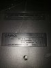
My wife last week decided that she wanted to teach our 4 year old keyboard. The only problem was that we didn't have a keyboard and that she didn't know how to pay one. I knew my dad had an old keyboard - Casio 465 Sound Tone Bank CT-638 that was just collecting dust so I figured that was very convenient, so I asked to borrow it. My wife went straight to Youtube and watched video after video of keyboard lessons. The keyboard worked great, no issues. She stayed up quite last the last week watching keyboard tutorials on Youtube! She was learning a lot and was showing our son a little bit everyday (as much as he would tolerate)

Fast forward to today, she goes to turn it on and the red power light comes on, but when you hit the keys you can barely hear any noise. Even with the volume on max, the sounds is very very faint, you almost cant hear it, you have to put your ear next to the speaker to pick up on it. So I Plugged in some head phones and same thing, very very faint music when you hit the keys, you can barely hear it.

I'm not sure where to start. I don't know if its a coincidence that after a week of "heavy use" something has gone bad. Im guessing it correlated.

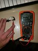
So the only obvious thing I could find was the power supply. The keyboard asks for 9VDC. My power adapter is rated at 9VDC 300mA. When I put my multimeter to it it reads 11.72 VDC. I'm not sure if that could have damaged something that it was almost 3 volts more than its supposed to be.

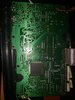
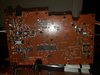
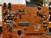
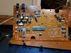
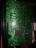
Other than that I'm not really sure where to start. I was trying to find someone with a similar issue online and I couldn't. I've uploaded some pictures below. Let me know what else I can do, I really want to fix this thing as it's my dads and so that my wife can continue to play and learn.

Thanks!
IMG-20210130-WA0013.jpg
IMG-20210130-WA0015.jpg
IMG-20210130-WA0016.jpg
IMG-20210130-WA0017.jpg
IMG-20210130-WA0018.jpg
IMG-20210130-WA0019.jpg
IMG-20210130-WA0021.jpg
 

Attachments

  • IMG-20210130-WA0012.jpg
    IMG-20210130-WA0012.jpg
    213.3 KB · Views: 12
  • IMG-20210130-WA0014.jpg
    IMG-20210130-WA0014.jpg
    163.2 KB · Views: 12
  • IMG-20210130-WA0020.jpg
    IMG-20210130-WA0020.jpg
    182.9 KB · Views: 13
  • IMG-20210130-WA0022.jpg
    IMG-20210130-WA0022.jpg
    201.2 KB · Views: 13
  • IMG-20210130-WA0023.jpg
    IMG-20210130-WA0023.jpg
    203 KB · Views: 13
Last edited by a moderator:

Harald Kapp

Moderator
Moderator
Your power supply is likely to be unregulated. I assume you measured 11 V without the keyboard being connected. When you connect a load (keyboard) the voltage will drop to around 9V. Most likely not an issue here. The keyboard will down-regulate from that voltage to a lower internal voltage anyway and the voltage regulator is likely to be tolerant to a bit of overvoltage.
Check the volume potentiometer for corret soldering. Nudge the lever to see whether this changes the volume.
If not, chances are something happened to the output amplifier stage (that big IC next to the output connector). You can poke around (carefully) with an isolated stick (popsickle stick?) to see whether a bad solder joint may be the culprit. And visually inspect all solder joints for quality. Re-solder the ones that look suspect.
Also inspect the electrolytic capacitors (the cylinders with the blue plastic shrink wrap and the metallic top) for visual signs of defects.

What experience do you have, which instruments do you have to probe further?

Thank you for your reply Harald Kapp. I tried nudging the main volume potentiometer level in all directions to see if it makes a change with the volume, it does not. The volume stays very very very faint (you have to put your ear up to the speaker or put headphones on to hear the slightest noise, and only than you can only hear a few of the higher pitch keys.

My experience is quite limited I'd say. I've soldered a fuse on vacuum cleaner PCB before. I've replaced and soldered a rechargeable battery in a electric toothbrush PCB before. I've used a multimeter a few times in the past to fix automotive electrical issues. So I am inexperienced when it comes to board level electronic components, but I don't give up! lol. I do own a digital multimeter. That is about the only equipment I own. I am open to buying more tools if need be to help me fix this issue.
I inspected all the solder joints on the board visually and I poked them all around with a popsicle stick, nothing changed. It seems like the solder joints are good. (as far as I can tell)

I visually inspected the electrolytic capacitors, they all look good to me, (no corroision, no deformities, they seem well soldered)

I'm just having trouble locating the output amplifier stage (that big IC next to the output connector) When you say output connector do you mean the headphone jack?

I've attached a picture below of what I think you're referring to, I'm not sure though.


Thanks again for your help :)
IMG-20210130-WA0025.jpg
 
Thank you for clarifying that for me Harold. I located that output amplifier stage beside the output. I poked around all the solder joints with a popsicle stick, made sure it was secured well, it seemed like it is, I visually inspected all the solder joints (they look good)

Can I test it with a multimeter somehow or would I need a schematic to know which solder joint to test?

Thanks for all the help
 

Harald Kapp

Moderator
Moderator
A schematic would be most helpful. Probably hard to find.
What is the inscription on that power amplifier chip I marked in post #4? Knowing what chip is being used there allows to check for correct operating voltages as a minimum check.
 

Harald Kapp

Moderator
Moderator
Read the last paragraph first.

It seems the chip is a CA5668 equivalent to LA5668. The datasheet is here. That is, contrary to my first assumption, not the power amplifier but a voltage regulator. Check it anyway.
With your multimeter measure the power supply as follows:
pin 7 (+) vs pin 4 (-)
pin 2 (+) vs pin 4 (-)
pin 6 (+) vs pin 4 (-)
pin 8 (+) vs pin 4 (-)
Repeat but measure against pin 7 and pin 9 instead of pin 4. Report your 12 measurement results. This will give an indication whether the power supply is o.k. Make sure you create no short circuits while measuring.
While you're at it, you could also verify that the supply from the wall wart is 9 V, as I explained earlier. Measure directly at the pins of the DC socket.

One other thing: The manual states that this keyboard has a power consumption of 4.5 W. Your litte 9 V/300 mA wall wart is undersized (9 V × 0.3 A = 2.7 W only). It may simply have died on you due to overload. In that case, the fault is not with the keyboard at all. Check with a more powerful wall wart 4.5 W at 9 V requires an output current of 500 mA or more.
 

VOT ? . . . ACH HIMMELL . . . .nein - NEIN - NEIN
. . . . der CA5668 icht bin der Voltages-es-es-es Reg-yum-er-la-ra-tor-er-er . . .
und der LA 4127 . . . . .icht bin der . . . .audio . . . OOOOOOM-PAH . . . . .OOOOOOM-PAH . .pa-pa mow- mow.

We can see that the power wall wart AC adapter now used by the unit is having the proper plug and polarity of input.
BUT is there any confirmed marking verifying that as being THE original and PROPER CASIO AD-5 . . . . AC line power adapter ? which is properly rated at 9VDC at ~ 1 amp.
Or posssibly you are unknowingly using some one of your past . . . . . scraped up . . . .cast off, answering machine or cable box or ? wall warts at its 12VDC and ~1 A.
If you refer to my added on spec sheet at the bottom of the photo, 11VDC is max DC power input for that LA4127 IC.
And you ran it for how many extended hours ?

I have marked up the LA4127's pin indexing from YELLOW RECTANGLE reference (dimple) of its pin 1. You need to initialy pre - locate the pin #11 as being the power input and + DC voltmeter connection and then either 1--- 5---10 as being metering ground connection.
You then power up and monitor that pin 11 voltage to thereby give us some clue then, so that we then analyze for it being the voltage regulator chip or the LA4127 AUDIO power amp as the fault.
Now . . .godoittoit . . . . .
PROCEDURAL HINT . . . .
Hold your meter probes right at their metal tips and brace each fingertips cluster right against the IC for thereby providing uber positional stability, and therefore no chance of slipping off and shorting into an adjacent I C pin. ( 'cause it then go BOOOOOM ! BOOOOOM !- - - yaka laka - - Sparkee-Sparkee ! )

No chance of the 12VC shocking you nor the imparted finger resistance upsetting resultant meter reading accuracy.

Your Marked Up Photo Referencing . . . . .
Casio-CT-638-PCB.png


Found that out and was typing while you re:)plied .


I been typing at the same time . . .TOOOOOOOO . . . .


73's de Edd . . . . .


Prayer:
"Oh Lord, give me patience, but give it to me RAT NOW !"


.
 
Last edited:
Read the last paragraph first.

It seems the chip is a CA5668 equivalent to LA5668. The datasheet is here. That is, contrary to my first assumption, not the power amplifier but a voltage regulator. Check it anyway.
With your multimeter measure the power supply as follows:
pin 7 (+) vs pin 4 (-)
pin 2 (+) vs pin 4 (-)
pin 6 (+) vs pin 4 (-)
pin 8 (+) vs pin 4 (-)
Repeat but measure against pin 7 and pin 9 instead of pin 4. Report your 12 measurement results. This will give an indication whether the power supply is o.k. Make sure you create no short circuits while measuring.
While you're at it, you could also verify that the supply from the wall wart is 9 V, as I explained earlier. Measure directly at the pins of the DC socket.

One other thing: The manual states that this keyboard has a power consumption of 4.5 W. Your litte 9 V/300 mA wall wart is undersized (9 V × 0.3 A = 2.7 W only). It may simply have died on you due to overload. In that case, the fault is not with the keyboard at all. Check with a more powerful wall wart 4.5 W at 9 V requires an output current of 500 mA or more.

I measured the mA from the wall wart, they are reading about 14mA, does this mean that the wall wart is bad?

IMG-20210130-WA0030.jpg IMG-20210130-WA0027.jpg IMG-20210130-WA0028.jpg IMG-20210130-WA0029.jpg IMG-20210130-WA0026.jpg
 

bertus

Moderator
Hello,

You can not measure the output current like that.
When you use a current range, you will basicaly short the output of the powersupply.
You can even damage the powersupply that way.
Current is measured between powersupply and load.

Bertus
 
Read the last paragraph first.

It seems the chip is a CA5668 equivalent to LA5668. The datasheet is here. That is, contrary to my first assumption, not the power amplifier but a voltage regulator. Check it anyway.
With your multimeter measure the power supply as follows:
pin 7 (+) vs pin 4 (-)
pin 2 (+) vs pin 4 (-)
pin 6 (+) vs pin 4 (-)
pin 8 (+) vs pin 4 (-)
R...............

I measured directly at the pins of the DC plug it reads about 11.5VDCIMG-20210130-WA0031.jpg
 
Last edited by a moderator:
Hello,

You can not measure the output current like that.
When you use a current range, you will basicaly short the output of the powersupply.
You can even damage the powersupply that way.
Current is measured between powersupply and load.

Bertus

Oh :/ jeez and I thought I was onto something lol. I will take note of that and never do it again!
 
Do note that back on your current test that you PROPERLY plugged into the 10A receptacle with your + meter lead BUT then had your selector switch NOT simultaneously being in the 10A range, as it should have been. . . . you had erroneously left it in the ma scale range.
Try that correction and then try again but then keep the metering across the plug for ONLY the time being needed to get a meter reading display.
Hoping that there is no internal fusing.
This 10 amp current range, with . . . . .fast . . . .monitoring, is the procedure that I have used for DEFINITIVELY testing AAA thru D dry cells for 75 years.
 
Last edited:
VOT ? . . . ACH HIMMELL . . . .nein - NEIN - NEIN . . . . der CA5668 icht bin der Voltages-es-es-es Reg-yum-er-la-ra-tor-er-er . . .
und der LA 4127 . . . . .icht bin der . . . .audio . . . OOOOOOM-PAH . . . . .OOOOOOM-PAH . .pa-pa mow- mow.

We can see that the power wall wart AC adapter now used by the unit is having the proper plug and polarity of input.
BUT is there any confirmed marking verifying that as being THE original and PROPER CASIO AD-5 . . . . AC line power adapter ? which is properly rated at 9VDC at ~ 1 amp.
Or posssibly you are unknowingly using some one of your past . . . . . scraped up . . . .cast off, answering machine or cable box or ? wall warts at its 12VDC and ~1 A.
If you refer to my added on spec sheet at the bottom of the photo, 11VDC is max DC power input for that LA4127 IC.
And you ran it for how many extended hours ?

I have marked up the LA4127's pin indexing from YELLOW RECTANGLE reference (dimple) of its pin 1. You need to initialy pre - locate the pin #11 as being the power input and + DC voltmeter connection and then either 1--- 5---10 as being metering ground connection.
You then power up and monitor that pin 11 voltage to thereby give us some clue then, so that we then analyze for it being the voltage regulator chip or the LA4127 AUDIO power amp as the fault.
Now . . .godoittoit . . . . .
PROCEDURAL HINT . . . .
Hold your meter probes right at their metal tips and brace each fingertips cluster right against the IC for thereby providing uber positional stability, and therefore no chance of slipping off and shorting into an adjacent I C pin. ( 'cause it then go BOOOOOM ! BOOOOOM !- - - yaka laka - - Sparkee-Sparkee ! )

No chance of the 12VC shocking you nor the imparted finger resistance upsetting resultant meter reading accuracy.

Your Marked Up Photo Referencing . . . . .
Casio-CT-638-PCB.png


Found that out and was typing while you re:)plied .


I been typing at the same time . . .TOOOOOOOO . . . .


73's de Edd . . . . .


Prayer:
"Oh Lord, give me patience, but give it to me RAT NOW !"


.


Hello Sir,

I followed your instructions and measured the voltage at the LA4127 AMP. I placed my red lead on #11 pin and than on #1, #5, and #10. They all read 9.13VDC.

Does this mean that the AMP is good?
 
Do note that back on your current test that you PROPERLY plugged into the 10A receptacle with your + meter lead BUT then had your selector switch NOT simultaneously being in the 10A range, as it should have been. . . . you had erroneously left it in the ma scale range.
Try that correction and then try again but then keep the metering across the plug for ONLY the time being needed to get a meter reading display.
Hoping that there is no internal fusing.
This 10 amp current range, with . . . . .fast . . . .monitoring, is the procedure that I have used for DEFINITIVELY testing AAA thru D dry cells for 75 years.


Ok I followed you instructions and did it fast. It stayed steady at that reading of 0.062 A
 

Attachments

  • IMG-20210130-WA0032.jpg
    IMG-20210130-WA0032.jpg
    120.3 KB · Views: 3
  • IMG-20210130-WA0034.jpg
    IMG-20210130-WA0034.jpg
    219.1 KB · Views: 3
Read the last paragraph first.

...............

Hi Harald, I've completed the measurements (assuming pin #1 is the one closest to the power plug)

pin 7 (+) vs pin 4 (-) = 0V
pin 2 (+) vs pin 4 (-) = 0.9V
pin 6 (+) vs pin 4 (-) = 1.2V
pin 8 (+) vs pin 4 (-) = 5V

pin 7 (+) vs pin 7 (-) = 0V (wasn't sure if I did this correctly, I just put both leads on pin 7)
pin 2 (+) vs pin 7 (-) = 9.13V
pin 6 (+) vs pin 7 (-) = 1.25V
pin 8 (+) vs pin 7 (-) = 5V

pin 7 (+) vs pin 9 (-) = 0.1mV
pin 2 (+) vs pin 9 (-) = 9.12V
pin 6 (+) vs pin 9 (-) = 1.12V
pin 8 (+) vs pin 9 (-) = 5V
 
Last edited by a moderator:
I currently don't have a more powerful wall wart 4.5 W at 9 V with an output current of 500 mA or more. All the thrift stores are closed at the moment (there is usually many available there) I will definitely try and find one so I can plug it in.
 
Last edited by a moderator:
Top