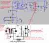
0.1μF feeding 500k ohms has a cutoff frequency (-3dB) calculated to be extremely low at 3.2Hz. We cannot hear below 20Hz and many speakers cannot produce frequencies below 35Hz.
I do not know the inductance values you have. 470pF might not be a good value for them.
Look in Google for an LC Resonance Calculator.
I cannot understand your broken English. Is there a forum in your country in your own language?
I do not know the inductance values you have. 470pF might not be a good value for them.
Look in Google for an LC Resonance Calculator.
I cannot understand your broken English. Is there a forum in your country in your own language?