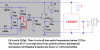
-
Categories
-
Platforms
-
Content
Yes, you make the same errors over and over and over and over and …..
I like your huge 0.01 Farads capacitors. They will kill all output sounds.
Why are the transistors powered from only 0.5 somethings?
Yes you right i make some version i must be 0.01µ, AND THE BATTERY 2V, but my problem is now i take from a book, the autput should be from C4, but i dont receive sine wave, why man, now detector is okey why i dont receive sine wave, can you help a little bit, what is wrong, why i don receive sinewaveYes, you make the same errors over and over and over and over and …..
I like your huge 0.01 Farads capacitors. They will kill all output sounds.
Why are the transistors powered from only 0.5 somethings?
Thanks but i build one with lm386 TO YOU WANT TO SHOW? but you you said is not correct the detector, rely i mean i make it like in foto, i with show you the fileWhich battery is 2V? V3? It is shorted to ground on your mess of a schematic.
I asked you to post how you connected the output of the discriminator to the LM386 amplifier and show all the details of your LM386 amplifier but you do not show them.
IS this one good detector, I DONT KNOW HOW TO CONNECT THE LM386, when i am nt sure he demulate the signal, look i put to inductor plarity, tell me please, where is the problemThanks but i build one with lm386 TO YOU WANT TO SHOW? but you you said is not correct the detector, rely i mean i make it like in foto, i with show you the file
LOOK i MAKE a new version of detector like in book, what you can say about this, is this fm detector in orde, after i gonna connected lm386 LIKE YOU SHOW ME?, IS ORGINAL FROM BOOK? IF THEY HAVE ERROR LIKE BOTTOM A I WILL FIX NO PROBLEM, I JUST ONE TO SHOW NEW VERSION AND TO WORK IN THIS VERSION? THANKSYou added the LM386 to an old radio schematic that was full of errors. The new schematic still has most of the old errors.
On the radio, Q1 is not powered by anything and is not connected to L1.
Audiguru i am whaiting from you, i changes, now what i have to do, and also signal is output from C5You added the LM386 to an old radio schematic that was full of errors. The new schematic still has most of the old errors.
On the radio, Q1 is not powered by anything and is not connected to L1.
This is my last version in change a lot, but i dont understand how to put C4 to gorund can you help i dont know(i know to put a simbol of ground) but i dont understand you, please helpMore mistakes:
1) Q1 is not powered since L1 shorts the DC from R5 to ground. R5 and maybe L1 will burn up.
2) V3 is not needed.
3) Why do you have R10? It is shorting most mid and low audio frequencies to ground because it is calculated wrongly and it is not needed.
4) C4 is not connected to ground.
5) You have the audio that feeds C8 grounded so there will be no sound.
6) You have the audio frequency way too high at 80kHz.
The schematic of the LM386 amplifier is shown in its datasheet. It uses a 10k volume control so C8 that feeds it should be 0.33uF.
AND WHAT TO TO POWER IT MANUAM? WITH RESISTOR FOR EXAMPLE MIN AND MAX?, I CHANGE THE VALU OF C4, THNX MAN, I TRY IS NOT WORKING HOW TO POWER LM386 AND Q1You changed the audio frequency to 1MHz which is not audio.
Q1 and the LM386 are not powered.
There is no volume control.
The value of C14 is one million times too small.
Try C4 both ways:
Everybody in this forum knows how except you.I TRY IS NOT WORKING.
HOW TO POWER LM386 AND Q1?
I WILL TRYEverybody in this forum knows how except you.