Maker Pro
Maker Pro

Explain why DMM reads 00.0 on negative side of circuit

Hello All,
Another question any help appreciated. Thanks in advance
 

Attachments

  • simple_circuite_question_3.jpg
    simple_circuite_question_3.jpg
    206.6 KB · Views: 18
That's actually really confusing.
Can you explain that again please?
All I can think of is the LED is acting as it should, a diode.
But as I couldn't decipher your question, or where you are probing, it's just a guess.

EDIT: LEDs don't have positive and negative legs.
EDIT2: Put the resistor before the LED and try your probing again. See if you get the opposite results on your DMM.
Martin
 
Last edited:
That's actually really confusing.
Can you explain that again please?
All I can think of is the LED is acting as it should, a diode.
But as I couldn't decipher your question, or where you are probing, it's just a guess.

EDIT: LEDs don't have positive and negative legs.
Martin

Thanks for your reply

"LEDs don't have positive and negative legs."
Yes they do. Positive is the anode negative is the cathode. https://www.westfloridacomponents.c...w-to-tell-which-lead-is-positive-or-negative/

My picture shows the negative leg of the led. I put the black probe from my meter in the negative power rail. I put the red probe in the hole on the negative led leg. My meter reads .474 which is the resistance of the 470 ohm resistor. This is all done on the negative side of the circuit as shown in the picture.

Now with the black lead still on the negative power rail if I place the red probe on the positive side of the circuit on the other leg of the resistor my meter reads 00.0 which means there is continuity, but I was wondering why it would not read .474 ohms like the positive side did.

I hope you are clear on what I am saying about the more positive side or more negative side of the circuit, which I point out in the picture.

"EDIT2: Put the resistor before the LED and try your probing again. See if you get the opposite results on your DMM.
Martin"

The resistor is bridging the negative and positive sides of the circuit on the breadboard see the picture.
 
Last edited:
I put the black probe from my meter in the negative power rail. I put the red probe in the hole on the negative led leg
That will measure the resistor only.
Now with the black lead still on the negative power rail if I place the red probe on the positive side of the circuit on the other leg of the resistor my meter reads 00.0 which means there is continuity, but I was wondering why it would not read .474 ohms like the positive side did.

Sorry you lost me. Please edit the circuit picture with connections from your DMM.
Also, LEDS as you already stated have anodes and cathodes. Which tells you which leg to connect to the positive and negative of a power source.
Martin
 
The circuit is not powered. I will try to explain it better.

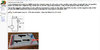
My circuit, the side with the short red jumper wire, going to the anode leg of the led, I am calling this the more positive side.
My circuit, the side with the small black jumper wire feeding the other leg of the resistor to complete the circuit, I am calling the more negative side.

The resistor is the bridging the breadboard center channel to complete the circuit.

If I keep my black meter probe on any negative power rail, and then I place my red meter probe on the more "positive side" on the "negative cathode side" of the LED "the side with the short red jumper wire" my meter reads .474 ohms.

If I keep my black meter probe on any negative power rail, and I then place my red meter probe on the more "negative side" the side with the short black jumper wire" on the other resistor leg my meter reads 00.0 to 00.3

I will upload more pics
 

Attachments

  • meter_reading_more_positive_side.jpg
    meter_reading_more_positive_side.jpg
    97.5 KB · Views: 8
  • meter_reading_more_negative_side.jpg
    meter_reading_more_negative_side.jpg
    89.2 KB · Views: 6
Last edited:
Ok we got there in the end.
What you are reading is perfectly normal. You are measuring the resistor. Then you are just probing a wire between the resistor and power source, it's a dead short for the DMM.

Martin
 
Ok we got there in the end.
What you are reading is perfectly normal. You are measuring the resistor. Then you are just probing a wire between the resistor and power source, it's a dead short for the DMM.

Martin
Why do you say it is a dead short? Isn't 00.0 on the ohm setting meaning continuity? Also there is no power going to this breadboard.
 
Yes, continuity means a loop without a break.
What you are doing *is* just putting the meter probes together.

Martin
Ok so here is where I am confused. Why am I getting a good resistor reading .474 ohms only on one side of the resistor, if the resistor is the bridge to complete the circuit?
 
fig9_multimeter-continuity-test-beep.jpg

This Is continuity.

Martin
 
Top