This is what I'm suggesting.
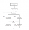
The main power supply generates a voltage around 30~35V at about 5A maximum. This voltage feeds into a buck converter with variable output voltage or current, which feeds through the H-bridge to the Peltier device.
Ideally the buck converter would provide a variable current, with the actual current determined by an input that would be driven either from a DAC in the MCU, or from a PWM output from the MCU that was then smoothed with one or more stages of R-C filtering.
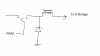
An alternative would be a voltage-regulating buck converter and a current monitor. The MCU would then control the converter's output voltage to achieve the desired current. I've shown the current monitor in the positive feed from the buck converter to the H-bridge but it could also be in the negative return of the H-bridge, for convenience. (A high-side current monitor is more complicated than a low-side current monitor.)
The H-bridge needs to be driven by a proper H-bridge driver IC that can generate the higher positive voltage for the top two MOSFET gates. Some of these driver chips are designed to monitor the current flow through the bottom MOSFETs to the 0V rail and they may be able to provide a convenient current feedback signal to the MCU.
When you change the polarity of the Peltier voltage by changing the control signal to the H-bridge driver, you should first ramp the buck converter voltage down to zero, or disable it completely, otherwise you may see a voltage spike from the converter during the dead time when the H-bridge switches from one state to the other. A reasonable amount of smoothing on the buck converter would probably avoid this, though.
My original suggestion was to combine the mains-powered supply with the buck converter, but you can use two separate converters if you want.
Comments Steve?
")