Summary: The problem I think I have - Multiplying DC 0 - 3.3v volt signal to 0 - 8v range
Is there a means to produce the alternating current required for a doubler circuit either with a voltage under 0.5v or with separate power / signal channels?
The PIFCO will also measure 0 - 240v AC, this might give more options?!
Detail: What I'm trying to achieve and why I'm probably asking the wrong questions!...
Hi,
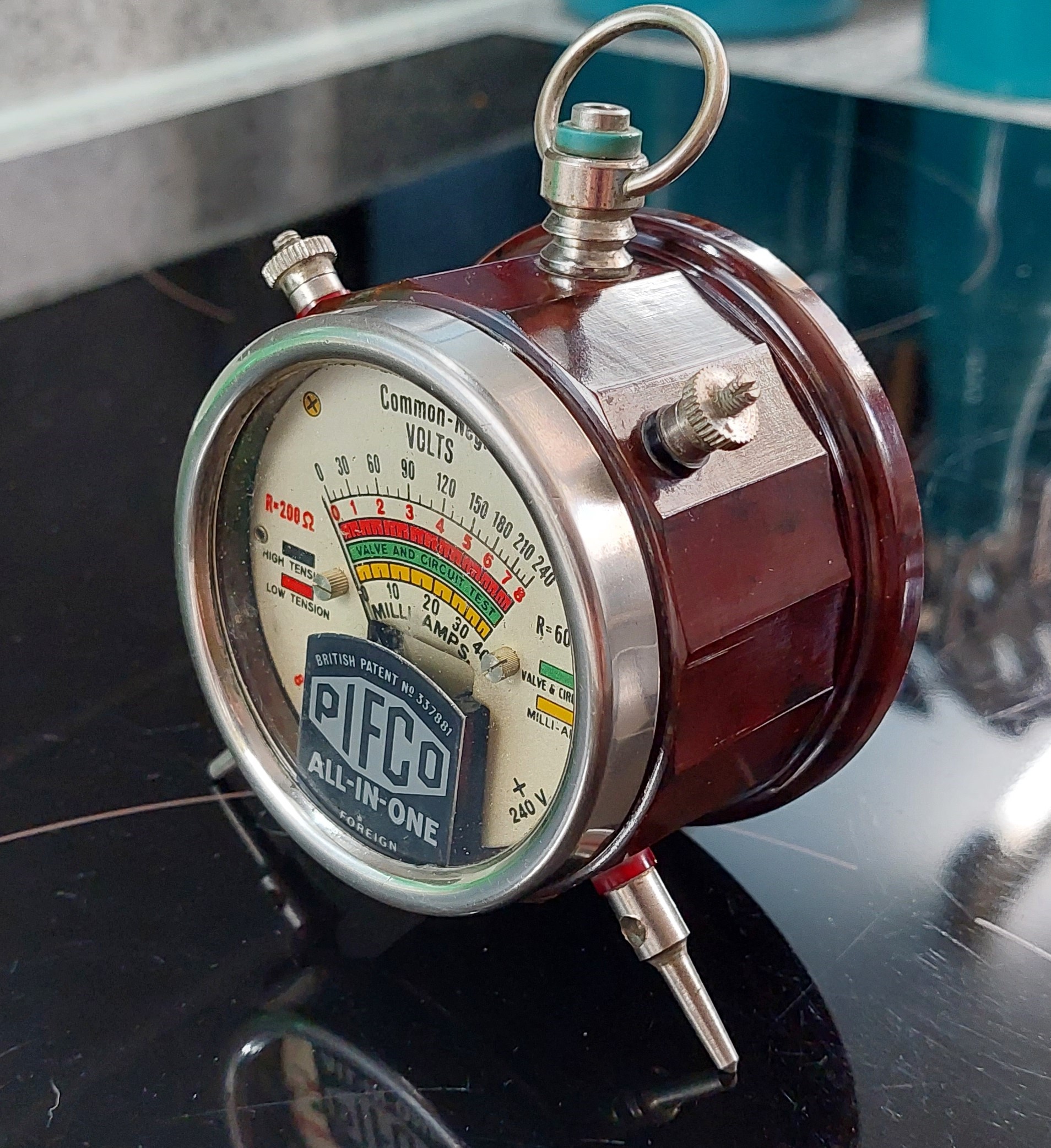
I have this beautiful, Bakelite, c. 1930s, all-in-one multimeter built by PIFCO.
I'd like to display it, but I'd also like it do something!
The specific something barely matters") maybe a CPU usage indicator, maybe internet bandwidth, maybe soil humidity for my greenhouse.
maybe a CPU usage indicator, maybe internet bandwidth, maybe soil humidity for my greenhouse.
Any of this data I can grab from my various smart home devices and can be pushed to, or pulled from, a controller through various software means.
The software side is something I can comfortably do.
The electronics is where I need advice!
I have several Raspberry Pi (of various vintages) lying around so I'd like to use this for the control.
I have proven the concept of software controlled voltage as shown in the video below.
(Edit: I'm being told by the forum that I cannot post an embedded video or video link. I'm sure you can picture the needle moving around points between 0 & 3.3v! https://i.imgur.com/xUpYkLe.mp4. Edit to the edit, apparently I can paste it plain, but not use the link function of the editor!)
BUT I'd like to use the whole range of the dial.
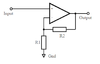
Googling suggests I need a voltage multiplier circuit. These seem to need either an AC source or a chopper device.
A 555 timer controlled voltage doubler / tripler / multiplier appears to be the answer at first look.
The circuits I have seen seem to suggest the powering of this IC needs to be minimum 5v. IC operating power and the signal to be multiplied appear to be one and the same.
Is there a means to produce the alternating current required for a doubler circuit either with a voltage under 0.5v or with separate power / signal channels?
The PIFCO will also measure 0 - 240v AC, this might give more options?!
Limitations:
Is there a means to produce the alternating current required for a doubler circuit either with a voltage under 0.5v or with separate power / signal channels?
The PIFCO will also measure 0 - 240v AC, this might give more options?!
Detail: What I'm trying to achieve and why I'm probably asking the wrong questions!...
Hi,
I have this beautiful, Bakelite, c. 1930s, all-in-one multimeter built by PIFCO.
I'd like to display it, but I'd also like it do something!
The specific something barely matters
maybe a CPU usage indicator, maybe internet bandwidth, maybe soil humidity for my greenhouse.Any of this data I can grab from my various smart home devices and can be pushed to, or pulled from, a controller through various software means.
The software side is something I can comfortably do.
The electronics is where I need advice!
I have several Raspberry Pi (of various vintages) lying around so I'd like to use this for the control.
I have proven the concept of software controlled voltage as shown in the video below.
(Edit: I'm being told by the forum that I cannot post an embedded video or video link. I'm sure you can picture the needle moving around points between 0 & 3.3v! https://i.imgur.com/xUpYkLe.mp4. Edit to the edit, apparently I can paste it plain, but not use the link function of the editor!)
BUT I'd like to use the whole range of the dial.
Googling suggests I need a voltage multiplier circuit. These seem to need either an AC source or a chopper device.
A 555 timer controlled voltage doubler / tripler / multiplier appears to be the answer at first look.
The circuits I have seen seem to suggest the powering of this IC needs to be minimum 5v. IC operating power and the signal to be multiplied appear to be one and the same.
Is there a means to produce the alternating current required for a doubler circuit either with a voltage under 0.5v or with separate power / signal channels?
The PIFCO will also measure 0 - 240v AC, this might give more options?!
Limitations:
- I cannot see any way to open the device without damaging it, so I'm not going to do this. Needs to work "as-is"
- Guage needs to cover the range 0 - 8v DC or 0 - 240v AC
- Raspberry Pi can produce only 0 - 3.3v
- Single, concealable, slender power wire to supply both controller (Rasp Pi) and any additional circuitry
- Raspbery Pi can also simultaneously supply a constant 5v (no programmatic control)
- £50 GBP (approx $60 USD) budget for additional components
- I have the knowledge of 2 weeks electronics at school 25 years ago! Basically an idiot!
Last edited: