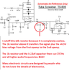
"Vr" indicates the 4.5V floating ground at both the 4.7K pictured AND the 10K you cut off.The TS-808 circuit has input and output transistors added and a multivibrator that flutters the audio back and forth between the clean and the distorted signals. The distortion circuits are exactly the same.
It is NOT the same
With the gain pot (500k) at zero, it provides a gain of 10.8, which stays under breakover of the diodes while producing a signal that can better survive the passive filters used for tone control before it reaches the buffer amp.
If you read the notes provided with the schematic, you will also see a reference to "SW" which is where you can edit out the flip flop in favor of a much easier to understand DPDT switch to do the same thing.
The last ones I built, I used 14 pin DIP sockets in the NFB loop to facilitate parts swapping, much like a breadboard.
the diodes can be replaced with LEDs in either symmetric or asymmetric arrangements. Resistors and pots for min gain and range of adjustment. Bypass caps .... a lot of modding and tone exploration can be done here.