Maker Pro
Maker Pro

Distortion Pedal Redux

Oh this brings back memories.
I reluctantly admit that many of those memories are of parts I didn't use right.
It looks like you've found some of the same old schematics I found back in the day. That's why you are fighting with it.
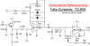
building from the ground up, your first objective is to get it to amplify clean. A modest gain of 2 or 3 is fine for proof of concept.
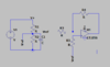
Just why is the ground leg of your negative feedback loop going to voltage _ instead of your Vref floating ground?
 
The diodes, 220k resistor and 100pF capacitor all connect between the same places (pin 1 and pin 2) so the sequence of them does not matter.
The crackling, spike and lasting for half a second is probably caused by the input 470nF capacitor value is way too high. The 470nF
is half a microfarad and it feeds 1M so it takes 0.5uF x 1M= 0.5 seconds to discharge. If you change the capacitor to 4.7nF or 1nF then it will still pass audio but discharge much faster.

1K resistor off of Pin 2 run
220nF capacitor off of pin 2 run
to ground
No. The 220nF capacitor does not connect directly to pin 2. The 1k resistor connects in series between pin 2 and the 220nF capacitor then the capacitor connects to ground.
 
VenomB. I will have to get back to you, although I don’t think k I am knowledgeable enough to answer your question
that much we can tell.
The objective it to fix the knowledge deficiency.
The question is just how to do that.
OpAmps have some basic rules. One of them is whatever the voltage is on the + input, it will change the output value to achive the same voltage at the - input.
Right now, you have + resting at 1/2 system voltage and the - at battery -.
It needs to rest at 1/2 voltage too.
 
This is a stripped down example so you can see it.
You are likely falling prey to the many stompbox sites that seem to get this wrong on purpose
 

Attachments

  • OpAmpRaw.png
    OpAmpRaw.png
    8.8 KB · Views: 5
Venom, you show a circuit with many parts that are not needed.
The opamp being used here has the correct voltages but the unused opamp has the wrong voltage and I do not know why.
You show a modern and expensive LT1056 opamp in a simulation that has no DC input offset voltage and no input current.
The DC gain in this circuit is 221 times which results in a small DC offset voltage the output, but the simulation uses a "perfect" opamp then shows no DC offset at the output.

But the opamp used is a cheap old NJM4558 that has a fairly high input offset voltage and input current that could result in a massive DC offset voltage at the output. This audio circuit does not want DC gain.
Hey, the DC offset voltage makes even more distortion. This circuit is for making lots of distortion.
 

Attachments

  • Venom.png
    Venom.png
    22.2 KB · Views: 4
Venom, you show a circuit with many parts that are not needed.
The opamp being used here has the correct voltages but the unused opamp has the wrong voltage and I do not know why.
You show a modern and expensive LT1056 opamp in a simulation that has no DC input offset voltage and no input current.
The DC gain in this circuit is 221 times which results in a small DC offset voltage the output, but the simulation uses a "perfect" opamp then shows no DC offset at the output.

But the opamp used is a cheap old NJM4558 that has a fairly high input offset voltage and input current that could result in a massive DC offset voltage at the output. This audio circuit does not want DC gain.
Hey, the DC offset voltage makes even more distortion. This circuit is for making lots of distortion.
It was the first thing in LT spice I clicked is all.
while the goal is to induce distortion, we do so from a clean baseline. It's the job of the diodes and the gain pot in the NFB loop to offend our audiophile sensibilities.
Ultimately, a distortion peddle that does not offer the option to run clean, by virtue of the gain pot, is undesirable. Often times in a signal chain, you will see a pedal like this with it's gain at zero, volume turned to 11, and the tone control wherever it floats the guitarists boat.
In this way, it sends a boosted, and tone sculpted signal into the front end of a tube fired amp where the hollow state hardware can put it towards rich meaty tones of thunder and singing leads.
This sounds like sheer lunacy from a technical point of view. But, left to the peddle alone, when the gain goes up, that meaty richness vanishes.
These circuits were my gateway drug to electronics. Believe me when I tell you there are scads of schematics out there that do not work as drawn. It looks like he's found some of them.
 
Venom, you show a circuit with many parts that are not needed.
The opamp being used here has the correct voltages but the unused opamp has the wrong voltage and I do not know why.
You show a modern and expensive LT1056 opamp in a simulation that has no DC input offset voltage and no input current.
The DC gain in this circuit is 221 times which results in a small DC offset voltage the output, but the simulation uses a "perfect" opamp then shows no DC offset at the output.

But the opamp used is a cheap old NJM4558 that has a fairly high input offset voltage and input current that could result in a massive DC offset voltage at the output. This audio circuit does not want DC gain.
Hey, the DC offset voltage makes even more distortion. This circuit is for making lots of distortion.
Here's how the people at Ibanez did it in what is arguably the gold standard of soft clipped distortion
 

Attachments

  • TS808.png
    TS808.png
    59.4 KB · Views: 6
h guys...well, ;let me finish building this one and see where we land. in the interim, Veb=nomB, if you have a basic schematic that you would recommend, please let me know.

Thank-you
 
The distortion opamp on the TS 808 has exactly the same diodes soft-clipping circuit as in this thread except it uses a very low value 10k resistor to bias it, then it needs the transistor emitter-follower at the input to increase the input resistance up to almost the 1M resistor here.

The circuit in this thread uses the very high input resistance of the Fet-inputs TL081 opamp to do it.
Electric guitar people use a pedal, not a peddle.
it also applies Vref to the non inverting input.
You have strung this guy along over three pages of failure and mediocre results, from a set of components that should just work.
its not hard man ... bring it up to floating ground, amplify it and cram it through some diodes, amplify what's left from that, strip the 4.5V with a blocking cap and ship it to an amp
 
Hey guys. I appreciate the help and advice. I don't think I have been strung along. This is a learning. experience for me, and failure is part of that. No, I don't think I'll build only one pedal; so perhaps the schematic you posted may be a future venture.

P.S. I don't know what floating ground means.
 
it also applies Vref to the non inverting input.
You have strung this guy along over three pages of failure and mediocre results, from a set of components that should just work.
Venom, you do not understand that the circuit in this thread does apply Vref to the non-inverting input, through the 1M bias resistor.
Then the input transistor in the ES-808 circuit you posted is not needed.
The failures and mediocre results were caused by wiring errors, not by the circuit.
 
I’m a novice and making all the expected errors. BUT, I have learned a lot and everybody here has been quite patient.
 
an
Venom, you do not understand that the circuit in this thread does apply Vref to the non-inverting input, through the 1M bias resistor.
Then the input transistor in the ES-808 circuit you posted is not needed.
The failures and mediocre results were caused by wiring errors, not by the circuit.
and the inverting input references battery -
in the TS 808, and most others I've cracked into, this input also references the floating ground (Vr in the 808 schematic) and not battery -.
Essentially, we treat them as we would a class B power amp, but in miniature, and let it pretend it's in a +/0/- supply via the voltage divider in the power supply, where we reference 0 as ground. In a single ended supply as we are limited to in these circuits, we just need to bookend the circuit in blocking caps to keep that Vref out of gear its connected to.
 
Hey guys. I appreciate the help and advice. I don't think I have been strung along. This is a learning. experience for me, and failure is part of that. No, I don't think I'll build only one pedal; so perhaps the schematic you posted may be a future venture.

P.S. I don't know what floating ground means.
you are working with a tiny amplifier that would prefer to be treated like a big one that would deliver an AC current to drive a speaker.
To do this, it uses a three point power supply where you have a +V, a -V and a 0V ground, the AC output is a product of the output stage using a pair of transistors that take turns feeding the output, alternating between V+ and V- to speaker + ... speaker - goes to 0V ground to complete the current path.
In our case here, we have a battery that just gives us a 0V and a +9V with no -V, so we have to lie to the op amp to make it think it is in a bipolar supply.
that is what the voltage divider in the power supply is for. It provides a 4.5V source that it will believe is the 0V ground common to class B amps. since it is not a true 0V ground, we refer to it as a "floating ground".
Sure, it never actually outputs an AC result by itself, just a fluctuating positive signal. This is why we use capacitors at the input and output of circuits like this, to strip Vref from the signal outside the circuit, so that it does not harm equipment it's connected to.
 
The TS-808 circuit has input and output transistors added and a multivibrator that flutters the audio back and forth between the clean and the distorted signals. The distortion circuits are exactly the same.
 

Attachments

  • opamp soft clipping.png
    opamp soft clipping.png
    38.7 KB · Views: 5
Top