Maker Pro
Maker Pro

Distortion Pedal Redux

DO NOT connect the + input of the used opamp to the 1M resistor, instead connect it to the two 100k or two 10k voltage divider resistors and the capacitor to ground that is there.
 
AG- I don't understand. (Maybe this is a mistake I have made all along). If you look at the attached schematic, and the area I outlined in white, it suggests that R41 (the 1M resistor) runs from thre juncture between the 10K and 10K resistors, and then travels down and runs to pin 3. So, I have always interpreted that as connecting the 1M resistor to pin 3. What am I missing?
 

Attachments

  • schematic2.jpg
    schematic2.jpg
    76.6 KB · Views: 9
AG, if I understand you correctly, you are suggesting I connect the + input of the used op amp according to the white arrow in the attached. if that is so, why is it not like that on the schematic?

Also, please clarify what I do with the unused op amp,; I'm confused again.
 

Attachments

  • schematic3.jpg
    schematic3.jpg
    77 KB · Views: 5
To my recollection, this is how I have always wired up dual op amps chips:

Run the 1M lead to the + In on the first and second op amp
Short -In from the second amp to Out of the second amp.

Have I been doing this wrong? I'm very interested in your answer, as this may be something I have been doing wrong all along.
 
R32 and R33 are the voltage divider that make the filtered 4.5V.
The 1M resistor feeds the 4.5V through the 1M resistor to the + input of the opamp that is used. The 1M is the same as the 1M of the input of a vacuum tubes amplifier. A guitar pickup is made to feed 1M or more.
The input resistance of a TL081 opamp is extremely high like a vacuum tubes amplifier then the 1M resistor is not reduced and the guitar pickup works well. But some 741 and 4558 opamps have a minimum input resistance of only 300k. 1M with 300k makes 230k which is too low. 1M with two 300k inputs makes 150k which is much too low.

DO NOT connect the + input of the unused opamp to the the + input of the used opamp. Instead connect the + input of the unused opamp directly to the filtered voltage divider at R32, R33 and C30.
 
Just to be clear:

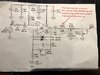
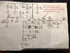
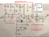
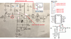
I understand not to connect the + input of the unused opamp to the the + input of the used opamp. But when you say, connect it instead directly to the filtered voltage divider at R32, R33 and C30- how can I connect it to three places? Or are you saying, that if I connect it to one of those places (for example, R32), I will be fine. And if so, where on R32? At the positive rail at the very top of the schematic, or just before the R32 reaches ground? Maybe a drawing might help, if that is not too much trouble.

And, to be double sure, the op amp that is being used, gets the IM lead at pin 3- right?

Sorry to be anal, but this is important as it may be one of the reasons why things aren't working for me.

Thanks!!!!
 
R32, R33 and C30 all connect together and make the filtered "half the supply voltage". Connect the + input of the unused opamp there.

The 1Meg resistor R43 connects to + input of the used opamp.

I think I mentioned before that the value of C23 (the input capacitor) is way too high at 470nF then it passes earthquake frequencies down to 0.34Hz that might clobber the signal. 10nF would reduce 16Hz and lower, 4.7nF would reduce 34Hz and lower, 1nF would reduce 160hz and lower. Do you have a solder slurper? Try changing C23.

I have used tens of thousands of a TL071 single, TL072 dual and TL074 quad audio opamps for hifi audio circuits and never had one that did not work. None were Chinesium ones. The TL07x is supposed to produce less hiss than a TL08x.
 

Attachments

  • half the supply voltage.png
    half the supply voltage.png
    341.7 KB · Views: 5
@AF- thanks. Yes, I do have a solder sucker. Do you have a suggestion as to the value of the replacement. The reason why I am asking is that I received an assortment of films capacitors and probably can match whatever you size you think would be better.
 
Changing the 470nF capacitor to a 1nF one will change the tone of the sounds. You might like it or maybe a value in between.
 
I'll try it. The good news is that I have yet to install that part of the circuit, so I don
't need to unsolder anything.
 
AG: I wired the entire circuit, except for the diodes part.

I used your recommended 1nF capacitor in place of the 470nF.

However, I am not getting any sound whatsoever.

Here are my Pin readings in volts:

Pin 1. 1.5
Pin 2. 3.1
Pin 3. 4.26
Pin 4. 0
Pin 5. 1.0
Pin 6. 8.74
Pin 7. 8.74
Pin 8. 9.3

Note that Pin 1- which is the Out, is not at the 4.5v that you had expected, so that may be a tell tale sign of an issue.

My rudimentary sense is that we either have a problem with measurements at the Pins, or the pots are not connected properly.

Thoughts?
 
As I think about it now, since I have not added the diodes, Pins 2 and 1 are not at all connected. Could that be the problem? Should;d they not be connected to one another?
 
Pin 1 and pin 2 on which opamp? A single opamp or a dual opamp?
If you are using the 4558 dial opamp then you need a schematic that uses it.
 
On the 4558D, Pin 1 is the out for the first op amp, and pin 2 is the - In.

Probably a rookie mistake. In my mind, I thought- I am going to install the diodes eventually- but I failed to realize that the Out to -In thing needs to be satisfied in the interim. Will report I once I have had a chance to make this change.

Bear in mind, that I have remapped the pins based o nt ne 4558D being a dual amp, rather than. a single. So when the schematic says 6 for out, I recognize that to me, it means Pin 1 for Out etc.
 
AG- I was in a rush but I quickly put a little wire to connect pins 1 and 2 and I got a reading of 4.4v on pin 1- which is what you were expecting. So, maybe this is a good thing. I won't know for sure till later, when I have time to do it properly.

Now I am thinking, I may as well go ahead and proceed with the diodes part of the circuit. If I solder Pins 1 and 2 together prior to doing that, I will need to unsolder them. So, I may as well go for the diodes thing.
 
I re-drew the schematic showing pin numbers for a dual opamp.
Many of your voltages are completely wrong.
Instead of the gain pot you should have the 220k resistor and the 100pF capacitor between pin 1 and pin 2. If the resistor or a piece of wire is missing then the voltages on pin 1 and pin 2 will be all over the place.

Shorting pin 1 to pin 2 results in a gain of 1, the output level is the same as the input level.
 

Attachments

  • distortion maker again.png
    distortion maker again.png
    380 KB · Views: 5
AG. Thank-you but the pin mappings are not an issue. I have always had those correctly mapped.

I have not posted the new measurements, as I have yet to fix the problem.

The gain pot is part of the original schematic. I can exclude it and use the 220K resistor and the 100 pf capacitor, as you suggested.,
 
Cam I put the 220K resistor after the 100pF capacitor?

In other words, in this order:

Diode 1
Diode2
100pF capacitor
220K resistor
1K resistor off of Pin 2 run
220nF capacitor off of pin 2 run
to ground
 
We are getting somewhere. I wired up the circuit as described above. The good news is that I am getting sound, and distorted sound. So it looks like the op amp and the diodes are working. However, I get some sharp crackling. In other words a crackling sound will spike over top of the regular sound, for half a second or so when I hit a chord. .
 
The circuit is working. I am pretty sure that the crackling sound is due to my wiring. Because the circuits I was doing kept failing, I began using the smallest pcb boards I have, just so I was not wasting the bigger ones. This made for very cramped components. I plan to now use a bigger board to avoid that problem. The only thing left, is to understand what sequence to put the 220k resistor in, as described above. Thanks for hanging in. Looks like we did it
 
Top