Maker Pro
Maker Pro

Distortion Pedal Redux

So, now that I successfully built a distortion pedal circuit, with the help of people here, I decided to try something else.

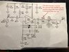
You will recall that I initially started with the attached schematic. Along the way, we made the following adjustments:

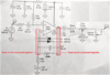
The voltage divider circuit was substituted with an alternate one.
I used a 4558D op amp, which is a dual amp, which is different from the single op amp identified in this schematic (so, we made some pin mapping adjustments, and buffered the second amp).

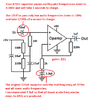
I finally received the 081 op amp called for in the attached schematic. I thus decided to try to build this circuit, exactly as shown in the schematic (now that I have the same op amp)

I built it with the op amp, the voltage divider and the diodes (according to the attached schematic) (I only installed the 500K pot so far).

I tested the circuit out and it doesn't work.

I measured my Pins in volts, and got the following readings:

1. 8.02 V
2. this number kept moving erratically, making it impossible to get a reading
3. 4.28 V
4. 0 V
5. 1.08 V
6. .494 V. Yes, that's decimal 4 9 4
7. 9.4 V
8. 8.58 V

These readings seem way off to me. As mentioned, I used the TL081CP op amp. What am I doing wrong. This should be much more straight forward than the dual op amps thing.

Thank-you
 

Attachments

  • schematic.jpg
    schematic.jpg
    76.1 KB · Views: 11
For a TL081 opamp:
Pin 1 and pin 5 should have almost the same low voltage.
Pin 8 should not have a voltage.
Pin 6 output should have the same voltage as pin 3 input.
It might not be an opamp. Where did you buy it?
 

Attachments

  • TL081.png
    TL081.png
    18.7 KB · Views: 5
Hi AG. I started from scratch. I don’t know why it worked this time. I think I may have had a short. I will post my new numbers soon. I am not 100% confident that all is perfect, but I was getting sound, so that’s a good sign
 
I need to start from scratch again.

I decided I was going to do a barebones version first. This meant working from the attached schematic.

Although I got that much of the circuit working, it turns out that I got myself confused going from the barebones, to the full blown version, and screwed up some wiring. I am going to rebuild in two phases:

Phase 1. I am going to build everything except for the diodes part.

I will pause and post my PIN measurements before going on to Phase 2.

Phase 2. Once I get that going, I will add the diodes.

Any thoughts?
 

Attachments

  • IMG_5103.pdf
    519.5 KB · Views: 7
I marked up notes on a previous schematic about your wrong capacitor values. This schematic uses different resistor values but your resistors are fine.
 

Attachments

  • distortion pedal redux.png
    distortion pedal redux.png
    44.5 KB · Views: 9
The bund has begun.

I have the voltage divider built,
I installed the socket for the op amp
I hooked up the + power to Pin 7
I hooked up the - to Pin 4
I ran the appropriate wire to Pin 3.

Without the op amp inserted into the socket, I am getting a reading of 4.5 volts at Pin 3. Does that sound right?
 
AG. Sorry for all the questions but I am proceeding oaths build faster that I had thought I would.

I now also have the 220 K resistor installed between pins 2 and 6.

Should I install the diodes and the 100pF capacitor ( C31 from original schematic), under the 220K resistor and before the 1K resistor (R46) and the 3.3 uF capacitor?
 
4.5V at pin 3 is correct.
The back-to-back diodes and 100pF ceramic capacitor are in parallel with the 220k resistor and connect to pin 2 and pin 6 of the opamp.
The 10nF input capacitor is film and the larger capacitors are electrolytic.
 
I have always used a film capacitor for the 100pF. I will have to look for a ceramic one. If I don't have ceramic, is film ok?

Thank-you
 
I have never seen a 100pF film capacitor, just ceramic at radio frequencies and low impedances.
Use it. Parallel to the 220k resistor, 7.3kHz and higher frequencies will be reduced.
 
Hmmm... I built this circuit without pots. I have no sound coming out.

Here are my Pin readings in Volts

1. 1.43 V
2. .509
3. 4.50 V
4. 0 V
5. 1.08 V
6. .2.5 and falling
7. 9.3 V
8. 8.45 V


I wonder if this has anything to with how I am wiring Pin 6. Pin 6 calls for it to branch out two different ways. One part of it goes to the 1Uf capacitor and then Out

The other part goes to the 220K resistor which then connects to Pin 2.

Because things get crammed, I use little terminal pins to extend Pins 2 and 6. In other words, I have a small wire running from Pin2 to a terminal, and a small wire running from pin 6 to a terminal. Picture two posts, with two holes in the middle of them.

Then, I wire up the diodes and and the 100pF capacitor in series between terminals representing pins 2 and 6. Then down the pin 2 thread, I continue with the 1K resistor, the 3.3uF capacitor and to ground.

ALSO....

Off of the terminal representing Pin 6, I connect the 1uF capacitor and continue to Out.

Could this be the cause of my issues?

EDIT: I have attached a sketch that will help illustrate what I am describing (note- I am not showing all the Pin connections. I am just focussing on pins 2 and 6 as described above.

On the sketch, the two dots that are green in color, represents the terminals (posts) I was referring to.

I am wondering if the way I connected the part in red ink, is causing the issue.
 

Attachments

  • IMG_5105.jpg
    IMG_5105.jpg
    196.1 KB · Views: 5
Last edited:
Because things get crammed, I use little terminal pins to extend Pins 2 and 6. In other words, I have a small wire running from Pin2 to a terminal, and a small wire running from pin 6 to a terminal. Picture two posts, with two holes in the middle of them.
Nothing should be crammed, instead the parts should be fairly close together and wired together as shown on the schematic.

Then, I wire up the diodes and and the 100pF capacitor in series between terminals representing pins 2 and 6. Then down the pin 2 thread, I continue with the 1K resistor, the 3.3uF capacitor and to ground.
No, the diodes are back-to-back in parallel and in parallel with the 100pf capacitor and in parallel with the 220k. They are all connected between pin 2 and pin 6. None of these parts are in series.
Pin 2 also has the 1k resistor in series with the 3.3uF capacitor to ground.
Your output capacitor at pin 6 is fine.

Your extremely important 220k (or 500k gain pot) negative feedback resistor is missing!
 

Attachments

  • dead opamp (2).png
    dead opamp (2).png
    452.3 KB · Views: 3
  • dead opamp voltages.png
    dead opamp voltages.png
    27.6 KB · Views: 3
Hi AG

My mistake. I meant to say parallel, but I said series., Rest assured, they are wired correctly.

you are absolutely right about the missing 220K negative feedback resistor. I think I was so fixated on setting up the Pin 2 and 6 posts, that I forgot to do that loop. I will fix that and report back.

Also, yes, Pin 8 is not connected to anything, so I wonder why I am getting 8.45v there. Maybe it's because the 220K resistor has yet to be installed?

In terms of my reference to cramming, it's because I am using a very small PCB board. So, it was a little tight. Once this circuit is working, I will rebuild mis on a bigger board with a view toward putting it into a casing

Thanks for your continued support!
 
Top