Maker Pro
Maker Pro

Distant Relay Module Circuit Help

Hi Guys,

Recently I have been formulating a relay module for my home automation system. I have finished wiring my whole house all the rooms. Unfortunately I couldn't wire any electrical wires but only some signal wires for the relay. So, I will be placing individual relay modules near to each of my home appliances and just signal them through a center control system which runs arduino as the microcontroller for switching part. Now the problem I have facing is to design a circuit which will provide me best delay free results for the relay on and off at a distant place.

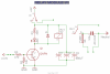
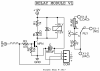
The schematic I formed is in the link here: https://imgur.com/a/B1i1W

Suppose the distance between the 5V relay power source and the relays are 3M to 5M. Also, the same goes for the arduino and the relays. So, the signal is also wired at this particular distance. I am using a 2N2222A Transistor for the signal switching part. So, guys please help me out how I can further improve the circuit design to get the best results out of my microcontroller and relay modules at a distance of 3M to 5M. I am willing to get fastest response possible with less jitter on either signal or the power source.

Thanks in advance...
 
Faster response? Faster than the speed of light? If there are any delays it will be as a result of your programming/controller, not the distance between switched units.

The relay schematic is wrong - use some ready-made relay modules designed for use on digital outputs. They can be purchased for less than the cost of individual component parts in most cases....
 

Fish4Fun

So long, and Thanks for all the Fish!
Hey Farukh!

As kellys_eye stated, you are much better off buying ready-made relay modules ... here is an ebay example: https://www.ebay.com/itm/NEW-5V-1-2...hash=item33dcaeb993:m:mma_l6pmGcnIAvIWlRTSkjQ

...Just one example of what's available ...

Not to be argumentative, but technically there is a delay introduced by relays (typically in the 100 millisecond time domain for small consumer oriented relays).... For an application like turning lights on and off, the delay is trivial; however early computers built using relays as switches were severely hampered by propagation delays introduced by relays. If you need switching to occur in less than 100mS then you might consider a thyristor based ("solid state") relay ... typical "on times" are in the 1uS time domain; however thyristor based relay "off times" are dictated primarily by line frequency as turn-off occurs only below some minimum current threshold (Assuming 50hz line frequency and a non-inductive load, typical turn-off time could still be as much as 20mS). In any case, for household lighting and appliances relay modules are cheap and easy solutions with an **almost** imperceptible amount of delay. If you are using LED lighting it is very likely the turn-on/off delays associated with driver start-up/power down latency could cause considerably more delay than the switch used to power them ;-)

Fish
 
Thanks for all the suggestion guys. But the problem is I mistakenly bought all 50 relays, caps leds and other equipments in want of making my own relay modules for this project. But I didn't thought it through earlier and this whole invest of mine is gonna get wasted if I buy the commercially available relay modules now. So, my only option is to make them. I have PCB boards etching and other tools all ready to go. When I bought these items I wans't aware of the commercially available relay modules because I was newbie at that time. So, the time delay won't be a problem even if the power source and signal source of the relays are at a distance from the relay right? If that's the case please help me correct my relay circuit so that I can build my own boards and implement them. Or else the whole stock will be a non-refundable waste.

Thanks.
 
forgot to mention that the arduino is just providing the signal for the relays to turn on or off. For the relay coil I am willing to use another power sources with a 5V regulator.
 
As already stated the small time delay is insignificant if you just plan to switch appliances on or off.
Electricity travels at 300 000 Km / second, or 300 million meters per second.
Reversing this, it will travel 1 meter in 1/300000000 second.
So even a 10-30 meter run will be faster than the average relay can operate.
The thing you may have to watch for is voltage drop over long runs, which could affect relay coil energizing correctly.
 
Based on the limited information in post #1, here is my guess at your schematic (BEFORE), and a suggested improvement (AFTER).

BEFORE, the transistor is acting as an emitter follower. This decreases the voltage across the relay coil to a max 0f 4.4 V. Also, there is a diode in series with the coil, and this decreases the max operating voltage even more, down to 3.8 V. It is not clear why you put the diode there, but I make a guess later. Important here is that the lower operating voltage causes the relay to respond more slowly than if the applied voltage were closer to 5.0 V. Also, there is no voltage gain in an emitter follower, so the risetime of the incoming signal is not improved. Compared to the actuating time of a relay the risetime probably is insignificant, but since you are focused on speed I bring it up for completeness.

AFTER, the transistor configuration is changed to a common emitter stage acting as a saturated switch. The saturation voltage is approx 0.1 V, increasing the relay operation voltage by 0.5 V compared to BEFORE. Also, the diode is repositioned as a suppression diode to prevent large voltage spikes when the relay is turned off. Since it no longer is in series with the coil, the coil voltage increases by another 0.6 V. With this circuit the relay coil sees approx. 4.9 V instead of 3.8 V. Finally, the transistor has voltage gain in this circuit so the rise and fall times at the collector should be faster than BEFORE.

ak
RelayDrive-1-c.gif
 
In the AFTER schematic there should be an additional resistor, from the transistor base to GND. This helps protect the transistor from damage when it is not connected to the Arduino output pin. Something between 10K and 47K.

ak
 
Hi @AnalogKid, Thanks a lot for your improved circuit. You guessed everything correct. I wanted to use the diode for stopping the reverse voltage spike from the relay. I learned a lot from your circuit. I am a newbie in electronics. Thanks again for the help.

By the way I have some 25V 1000uF and 25V 680uF polarized caps in my stock for this project. I was planning to use them on the relay modules 5V and GND so that the voltage drop along the distance won't effect much. What cap should I use? and how many of them? on the relay voltage. And does the arduino Digital signal needs a small cap or something? And should I join the voltage source ground and arduino ground? Some people out there were suggesting to get a common ground. But am really not sure why. And from the base of the transistor what resistor value to be exact should I use? And can I ground it on the voltage source ground at the emitter of the transistor or should I ground it with arduino ground? What is the method of estimating this resistance value? And the last thing is that I also had couple of 10uH inductors. Can those be used to further improve this circuit?

Let me know in detail.

Also, if possible let me know using what software you designed those circuits? And suggest me some good free software which is available for making this kind of schematics, pcb design and simulation? I am so newbie to these that I hand drawn my circuit on post #1.

Thanks.
 
And also if possible explain to me why you used the 470 Ohm resistor in between the arduino pin and base of the transistor and why the 220 ohm resistor on the LED light. How you calculating these values? Just very curious to know.

By the way the transistor I am using is 2N2222A. Is this transistor similar to the one you showed in the circuit diagram which is 2N2222?
 
2N2222, 2222A, 3904, 4401 - all equivalent in this application. Cross check - look up the coil resistance, calculate the coil current at 5 V. The transistor collector current rating must be twice this for decent reliability.

No need for a cap on the arduino signal line.

Either electrolytic is fine for decoupling power to the remote module. Place it close to the module. Unless you are using 30 GA wire, the voltage drop will be millivolts.

Because the transistor is part of both circuits - the signal circuit from the arduino and the power circuit to the relay, the arduino ground and the power ground must be the same. Extending the 5 V and GND from the arduino power oins to the relay circuit is ok; so is running the relay 5 V and GND directly to the power supply where they join the wires to the arduino.

No inductors; inductors bad (in this application).

Eagle software gets good reviews on this forum.

Unlike your original emitter follower circuit, the common emitter circuit needs something to limit the base current to a safe value. Something between 5 mA and 10 mA should get you solid saturation without overheating the base-emitter junction. A 5 V arduino output making this current will sag a little, so I estimated 4 V for the output. The transistor Vbe is 0.6 V, so that leaves 3.4 V across the resistor. 470 ohms is a very common value and yields approximately 7 mA of base current. If the relay coil requires more than 150-200 mA that might be a bit light, but it is a good starting point.

A generic red LED has a forward voltage of around 1.8 V and a nominal continuous operating current of 20 mA. It needs an external device or circuit to limit its current to a safe value (sound familiar?). Ohm's Law again. Assume the voltage drop across the saturated transistor (Vcesat) is 0.1 V. 5 V - 0.1 V - 1.8 V = 3.1 V across the resistor. 220 ohms is another very common value, and yields an LED current of 14 mA.

ak
 
I am using 24AWG wire so I will probably through a cap near to each of my modules. But how to know which cap value should I use? The voltage I am dealing with is 5V. Putting a 25V cap is just overkill isn't it? But will work perfectly fine right? What about the uF? Is there any uF limitation for this circuit? Or any value will do the same?

Actually I have 50 equipments in the whole house which will run on 50 relays. It is not possible to draw all the 50 relay coil currents from my single arduino board. That's why I am using another power supply for powering the relay coils. @AnalogKid you said "so is running the relay 5 V and GND directly to the power supply where they join the wires to the arduino." Does this mean I have to join both the 5V and GND wires from the power supply and the arduino? I mean to say VCC of arduino connected to the positive 5V of my power supply and both grounds connected? Or only the grounds are joined together? not the 5V and VCC?

I will try eagle today and also share my experience on this forum.

Can I find the relay current by measuring the coil resistance using my multimeter? and ohms law? How to relate this current with the base signal current? I used fastlad online circuit simulator and tried out the circuit above. When I used 5V on the base signal the current flow was around 9mA and the coil current was 245mA. When I turned the signal voltage down to 3.3V which is also a volt that can be supplied by arduino VCC, the base signal current became 5mA which is safe according to the range you have provided. But that slightly drops the current used by the coil at about 241mA. So, I am a bit confused here what's actually happening.

By the way what about the base to resistor to GND connection for the safety of the of the transistor? What GND should I use here? And I should calculate the resistor value by taking in account of the 5mA or 9mA signal current and the voltages right?
 
The final schematic I came up with is in the attachments. Please provide your suggestion guys. Thanks.
 

Attachments

  • Relay Module V1 - Schematic.png
    Relay Module V1 - Schematic.png
    330.7 KB · Views: 63
The final schematic I came up with is in the attachments. Please provide your suggestion guys. Thanks.

HI

Just my two cents....but if your planning to use long wire runs and small gauge wire, I think you'd be better off using a higher voltage level, like 12 volts for example. It helps overcome the wire resistance, oxidation, etc. Just an FYI, most commercial wired burglar alarm systems use 12 volt supplies with small gauge sensor wiring.

eT
 
What is the resistor and cap supposed to be doing on your relay output contacts? No need for anything there other than the c/o contacts. Why the extra fuse, no need for that either as main supply would already be protected by a fuse/circuit breaker. Just be aware that in most countries it is a requirement to have additional equipment certified for mains connection as well as certified electrician do the actual work of installation.
 
Well that's a simple snubber circuit there. In my country there is no main connection safety measurements. That's why I did put this simple fuse and snubber circuit to protect my relay module from surges.
 
Top