Maker Pro
Maker Pro

Battery powered Current sink with low voltage cutoff

Found a solder bridge by R4. Repaired it but still stays on check the new voltages…
I read from spec. the 2N700 Gate Threshold Voltage VDS = VGS, ID = 1 mA between .08v and 3v
From the schematic the gate of QH is 1.1v close, maybe no cigar?
 

Attachments

  • BPCS9B Voltage.png
    BPCS9B Voltage.png
    34.1 KB · Views: 204
Last edited:
Sorry left out a line.
NEW->I became suspicious of MOSFET QH so I replaced it with a MTP3055 that I had lying around (I know overkill) and guess what, yes, it worked.

That makes 3 bad MOSFETS how can it be? Any way do you think I should leave it in or replace it with a smaller one?

So, now the testing, adding of meters, enclosure etc. It seems you design was right from the start. I ran into 2 solder bridges, 3 bad MOSFETS, and a deficiency of knowledge,
but I’ smarter now thanks to you.

Regards,
Greg
PS use Kris layout 4 (has less errors)
 

Attachments

  • Constant Current Load.GIF
    Constant Current Load.GIF
    43.1 KB · Views: 161
  • Kris layout 4.gif
    Kris layout 4.gif
    35 KB · Views: 161
Last edited:

KrisBlueNZ

Sadly passed away in 2015
OK, I'm glad you've got it working.

I won't check your layout drawing... since it's working, there's no need.

I would replace the MTP3055 with a 2N7000. The 2N7000's minimum Vgs threshold is 0.8V, not 0.08V. The gate voltage in that circuit should be less than 0.8V. Perhaps there is still an error.

Try this. Set the switch to AUTO, short QH from drain to source, remove the SNK voltage source, and measure the following voltages:
1. TLE2022 pin 1
2. Top end of CH
3. QH gate.
Those three voltages should follow a ratio of 3:2:1, for example 1.2V, 0.8V and 0.4V respectively. This is because of the three 10K resistors. If they don't, there's an incorrect resistor or a wiring error somewhere.
 
Hi, I replaced with a 2N7000 you are right .8 not .08
here are the findings;
1. TLE2022 pin 1 43.7 mA
2. Top end of CH 29.2 mA
3. QH gate. 15.1mA
Pretty close.
I tested it and it turns off within 0.001v Really good. The scope also looks good.

One question, I buffered a meter with a LM 358 (ran out of TLE2022) as a voltage follower by connecting the negative pin 2 to the output pin1, and have the switch wiper connecter to positive pin 3, and get really strange readings.

Switch position 1 = Battery voltage Pin3 = 10.06v Pin1 =8.84V <-REALLY STRANGE??

Switch position 2 = Cutoff voltage Pin3 = 3.02v Pin1 = 3.02V

Switch position 3 = Input SNK voltage Pin3 = 3.42v Pin1 = 3.43V

How could this happen?
Regards,
G
 
Last edited:

KrisBlueNZ

Sadly passed away in 2015
1. TLE2022 pin 1 43.7 mA
2. Top end of CH 29.2 mA
3. QH gate. 15.1mA
You mean mV not mA, right?
Switch position 1 = Battery voltage Pin3 = 10.06v Pin1 =8.84V <-REALLY STRANGE??
The op-amp output won't swing all the way to the positive supply rail. Especially for the LM358 which is a very old device, but the TLE2022 will not swing all the way either.
Your best option is to buffer the cutoff voltage, and switch the meter input between +BATT, buffered cutoff voltage, and SNK voltage. (There's no need to buffer the SNK voltage, nor to buffer the battery voltage.)
An LM358 has a significant input offset voltage; typically 3 mV at room temperature but up to 7 mV (for the TI device, at least) at room temperature. That's why I suggested the TLE2024, the quad version of the 2022.
 
Thanks, that all makes sense. I heard there is a OP-AMP that would swing rail to rail. I’ll look on DIGIKEY and see if I can find one. That would save me a lot of soldering. I’ll post pictures of the project as I go.
Thanks again, I forgot about the offset on OP-AMPs.
 

KrisBlueNZ

Sadly passed away in 2015
Yes, you can get op-amps that swing rail-to-rail (or very close to), as long as they're not heavily loaded. But as I explained, you don't need it. You just need to buffer the cutoff voltage; the other two voltages (battery voltage and SNK voltage) don't need to be buffered.

Actually you can avoid the need for a third op-amp by using an emitter follower (transistor) as the buffer. It would add a DC offset of about 1.3V (using a Darlington) and that would require a change to the reference voltage. It's a valid and simple solution though. I can draw up the changes, but first I need to know the switch-off voltage range you need. I have assumed 4~8V. Is that right? Do you want to change either of those limits?
 
Thanks Kris,
I have already added the 2nd IC and all of the wiring. I would, however be very interested (on a learning stand point) to see your transistor emitter follower. It’s always good to acquire knowledge. Oh, and by the way please don’t spend too much of your time on this as I have already added the 2nd op-amp.
A quick Google of transistor emitter follower, gave me hundreds of hits. As far as switch off voltage range I would like to set it to about 1 volt, in order to test most batteries.

On another note, I’ve had a battery powered voltage source (that I put together from multiple sources) for about a year, and find it most helpful. I’m going to add a few bells and whistles to it, and build a new version, after completing this project.
I’ll post a schematic as soon as I get one drawn up. By the way I use EAGLE software. I works well and is free. I’ve made many circuit boards using it.
Regards,
Greg
 
Last edited:

KrisBlueNZ

Sadly passed away in 2015
OK, you want to be able to adjust your switch-off voltage down to about 1V. What about the maximum limit?
 

KrisBlueNZ

Sadly passed away in 2015
OK, here's the modified circuit.

attachment.php


I increased the 8V reference to about 8.7V because there's about a 0.7V drop in the emitter follower (QB).

The emitter follower acts as a buffer with a reasonably constant voltage drop. The voltage at the emitter has a much lower impedance than the voltage from the "set turnoff voltage" potentiometer and will not be affected significantly by the connection and disconnection of the meter.

You would need to adjust the two trimpots in series with the current and voltage setting potentiometers to get the correct range if you make this change. If you're only building one unit, it makes sense to stick with the extra op-amp, since you've already done it.

Look up "emitter follower" on Wikipedia for more information.
 

Attachments

  • GREGFOX.005.GIF
    GREGFOX.005.GIF
    20.1 KB · Views: 251
Boy, this simple project got really complex. I like what you did, it's even easier than a op-amp, but I think I'll stick with the extra op amp (because it's there). I want to put this together and get started in my favorite project, and that would be the battery powered lab supply.
As soon as this is completed I'll draw it up and post. The one I made a year ago has been really useful.
 
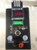
At last it’s time to put this project to bed. I tested it up to 2 AMPS, but limit the SNK to 1.5 Amp. The Voltage turn off is clean and within .002V as best I measure with a data logger. The unit draws about 40mA mostly due to the meters.

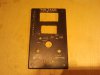
Looking back I guess we should have incorporated a timed turn off for the meters to save power, but I’m using 14500 LiPo batteries rated at 800mA. If you could get 500mA out of them before charge, you would have about 12 hours use. If you turned off the meters, you would have days. This could be done with a simple DPDT toggle, but I ran out of room and as one can see, it’s very tight inside.

It should be noted both Kris and I had different designs. My design used a single push button for on and off, and a Opti for turn off. It worked but I liked Kris’s design better so that’s the design I settled on. A slight difference, Kris uses a Ammeter, while I use two voltmeters. For current I measure the voltage drop across the 10, 1-watt 10 ohm resistors in parallel (1 ohm).

All credit should go to Kris for this design.

Regards,
Greg
 

Attachments

  • 2013-05-07 15.15.30.jpg
    2013-05-07 15.15.30.jpg
    145.7 KB · Views: 194
  • 2013-05-12 12.39.46.jpg
    2013-05-12 12.39.46.jpg
    122 KB · Views: 213
  • 2013-05-12 14.42.44.jpg
    2013-05-12 14.42.44.jpg
    143.6 KB · Views: 203
  • 2013-05-12 21.16.07.jpg
    2013-05-12 21.16.07.jpg
    147.6 KB · Views: 211
  • 2013-05-13 11.42.04.jpg
    2013-05-13 11.42.04.jpg
    133.5 KB · Views: 167
Top